


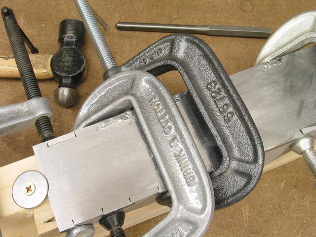
I used a three-axis CNC milling machine to make the sides, sole, lever cap, one adjuster part, and the mortise in the infill for the adjuster. (See Anilam CNC programs.) First I printed a full-size side profile and taped it to 5/32 precision-ground low-carbon steel stock. When using 2" wide steel, there's no waste, but if your stock is wider, align the top edge of the paper profile against a clean edge. (I know this means more cutting.) This way, you'll have a good reference edge against the bottom of the milling vise for cutting the tails. Alternatively, if you want the bottom of the sides to be the reference edge, you'll need to align the bottom edge (when held upwards in the vise) perfectly horizontal somehow. Then I cut just outside the line with a handheld jigsaw using a metal cutting blade. It's best to leave a longer top reference edge, so I left the topmost inner curve uncut until the tails were milled. Using a jigsaw is slow going, since you need to stop often and let things cool off. A hacksaw may be faster, especially when you don't have to follow curves. Refine the profile with files, to less than 1/16" of extra stock. The dovetails in the sides should be made before finishing the upper curves, and before milling the sole's pins. You can save some time, especially if cutting by hand or using a manual milling machine, by ganging both sides together and cutting both sets of tails at once. When milling the sole, you can test-fit the corresponding side, making adjustments while you've still got the part fixtured and located. (Assuming it's tight, and not loose! I avoided wasting a lot of metal by making test parts of plywood first to tune the process.) There's no advantage to ganging the sides when cutting the upper profiles, since the chamfers need to be cut individually, and the same setup is used first for the profile, and then for the chamfers. It's tricky holding the sides for this operation so that the clamps are clear of the tool path. Don't drill the infill-rivet holes until the infill is in place. The holes for the lever-cap pivots and for the grub screws that act as blade spacers could be drilled now, but perhaps better precision--especially critical for the lever cap--could be maintained by drilling after the sole and sides have been connected. As shown in the drawings, I left .050" of extra stock at the ends of the tails for peening, and .020" of extra width on each side of the sole's pins also.
Rivet the throat plate onto the sole before attaching the sides.
For the (3/16") rivets, I made a guard for my numerous errant hammer
blows by drilling a 1/2" hole in thin (.050) steel, and centering it
over the rivet. This really reduced the amount of filing and lapping
later. Don't countersink too much for your rivets! No more than
about .22 outer diameter (for 3/16 rod) is enough. I made the slot
for the iron after the sides were on, and that wasn't clever. Getting
your tools way down into that gully is a challenge. Rough out the
slot by line drilling and filing, saving wear and tear on those small
end mills. Leave the slot plenty undersized for now, as everything
you do from now on will make it bigger; you'll want to have very precise
control over the tightness of the mouth in the very final stages of
tuning the plane.
|
|
|
|
|
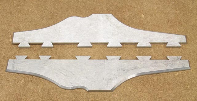
The body of this plane is made from flat steel plates, joined by
doubly-splayed dovetailed joints peened together. The dovetails are
very similar to traditional wooden ones; the tails are cut into the
sides, pins on the sole. With wood-style dovetails, the bottom
surface of the sole would have notches on either edge which are
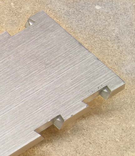
angled perpendicular to the sides. The difference appears when you
make a second cut which opens the roots (i.e. inbound from the
edge's outer face) of the pins by another 15°, but only on the
bottom of the sole. If you used a small three-square file, you'd
remove a small triangle; my CNC technique involved a 60° dovetail
mill, which I brought sideways, forming a triangular "tooth" into
the base of the pin's wall (the sole being held vertically), then
raised the mill at 15° off vertical. This leaves the pins
looking like more tails from the bottom, and a parabolic void when
viewed from the front and rear of the sole. Note that if 75°
dovetail mills were available, this would be easier and wouldn't
require CNC for the simultaneous two-axis move.
See Badger Pond post on
making secondary bevels.
 |
 |
 | |
Use 8-oz and/or 4-oz ball-peen hammers, and a round-nosed "roll-pin"
punch. The largest common size is for 5/16" pins, and it works well
for peening. The larger hammer is useful for riveting, especially
where fine control isn't needed. The smaller hammer size is better
for peening the dovetails, and the punch is good for precision work,
such as coaxing metal into the very inside corner of the dovetails.
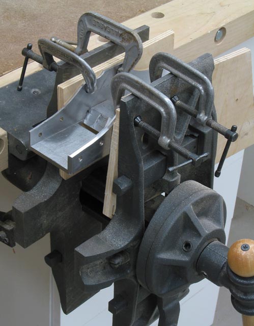
A peening buck can be made of 2x4s, jointed and glued, then milled
to exactly square at a width a few thousandths shy of the inside
wall-to-wall dimension. A notch is needed to clear the throat
plate. I screwed the sole onto the buck at the front and rear using
big washers and drywall screws. Shim the top of each side out by
.020" to correct for the springback which will occur. I have
heard of other people who got up to 1/16" springback. When
peening, I placed C-clamps fore and aft of where I was working,
maybe three or four total, cinched really tight, and had no problem
with things moving. Furthermore, I just used my workbench, not an
anvil. It was extremely beneficial (this being my first dovetailed
plane) to make some practice dovetails and rivets out of scraps before
trying my technique on the final parts.
 |
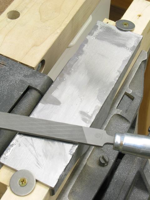
Clean your files often! Or better yet, pack the teeth with powdered chalk. Unlike wood, chunks of swarf stuck in the file can make serious gouges in your nearly-perfect surface. The Grobet Multi-Kut is very good in this regard--it has deep "gullets" to carry metal shavings out of harm's way, but still cuts fast and smooth. Other filemakers have similar models, e.g. Nicholson's Magicut.
In Response To: Insights from making infill plane (long) (Jim Yehle)
"I just heard of packing the file's teeth with chalk--is this the
reason for that practice?"response from Badger Pond:
Clay
< Metalsmiths often fill a files teeth with powdered chalk to prevent
clogging when filing soft metals especially brass. In my experience,
it works well even for harder metals like steel. It prevents the
filings from getting stuck in the crevices between the teeth and from
sticking together. I think that it does slow the cutting action
somewhat making it behave as if it had a slightly finer cut than it
actually does. I consider it a savings overall though as I rarely have
to worry about cleaning the file or using one that is clogged and
cutting poorly. You have to rechalk them occasionally if you are doing
lots of filing. The finer toothed files and double-cut files are more
prone to clogging and benefit most from this technique.
 |
 |
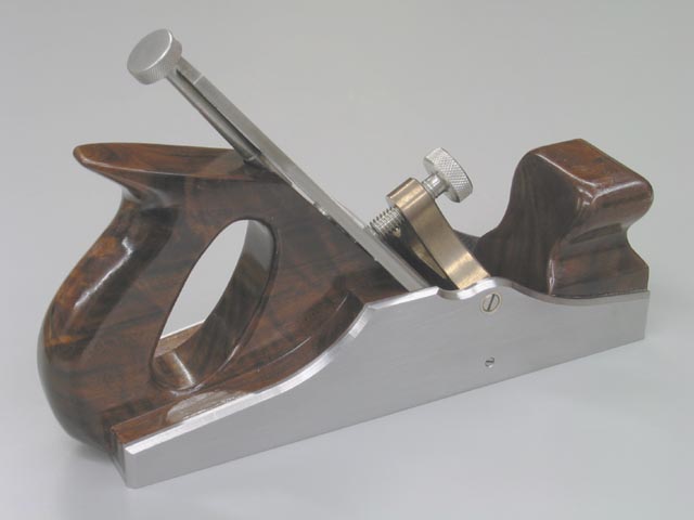
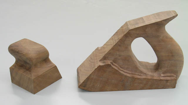
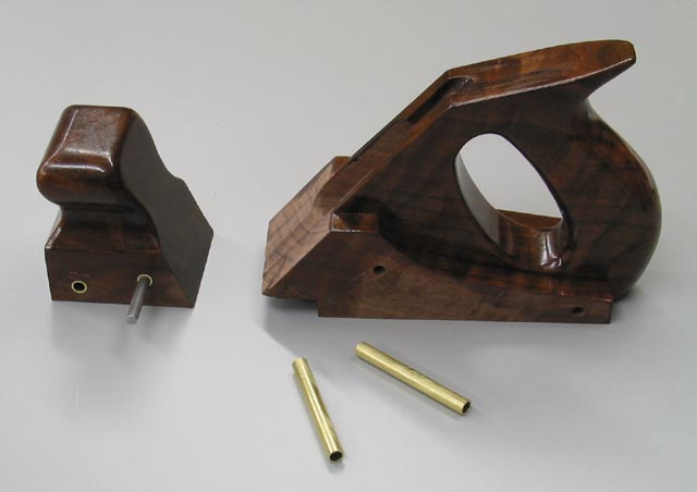
I used a closed handle design, mostly for a place to house the
adjuster. Open-handled rear infills typically use one hunk of wood
for the handle, and one for the front, with a big mortise for the
base of the handle. But with a closed handle, it seems to make
sense to continue the handle piece all the way forward to the iron,
and sandwich two sides onto it. It would be nice to use a single
piece of some dense exotic wood for the tote, but tracking down a
9/4 chunk of 5" wide stock to make it all out of one piece is not
easy. Besides, you end up making a lot of very expensive sawdust.
So laminating the tote vertically is a workable option. I have
heard of good results using both epoxy and polyurethane (Gorilla)
glue, expecially when using oily tropicals like cocobolo. As far
as the shape, I scaled up photos and drawings of many infill planes,
printed them, taped them onto scrap 1" cherry, roughed them out with
bandsaw, forstner bits, jigsaw and roundover bits, then smoothed and
refined them with rasp, file and sandpaper. This gave me a feel for
the shape I wanted.
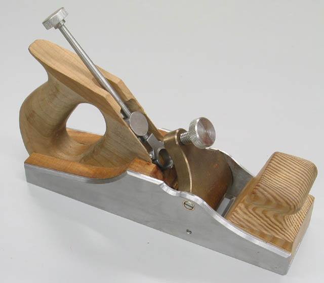 |
The final tote is just shy of 1-1/8" thick, because
it's more comfortable, and there's more room to house the adjuster.
Whereas open handles give a broader opening for larger hands, it's
more of a challenge for closed-tote designs. I like to at least
have the option of putting all four fingers inside the handle. With
a York pitch angle, and given the relatively large (for a smoother)
9" sole, it opens up the space at the rear, so you don't need to
hang the handle way off the back, but it's still best to take the
bottom of the hole nearly to flush with the sides to buy more room.
Now how about grain orientation? As near as I can tell, tradition
has it running straight fore-to-aft. For the rear infill, that
certainly makes sense, for strength reasons, and also because you
don't want shrinkage between the bed and the first infill rivet
("cross pin").
 |
 |
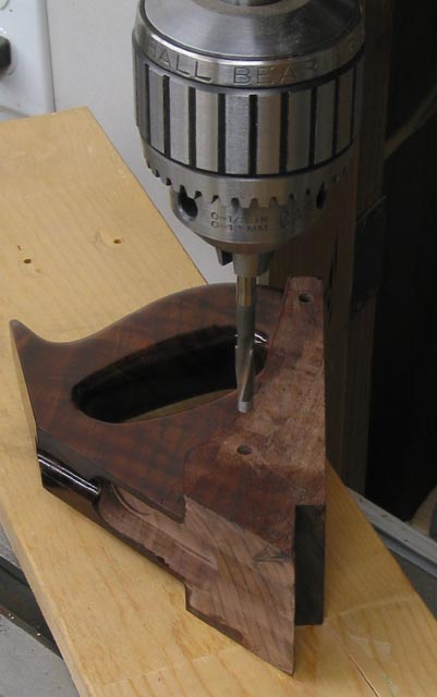
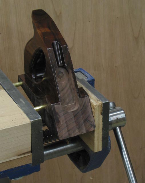
Install the infill into the shell. If you didn't shim the tops of
the sides out far enough during peening and ended up with springback
like I did, you will need to yank them (gently!) apart for this
step. Position the infill pieces precisely how you want them, then
drill and ream through the entire width (both sides and infill) to
the diameter of your cross-pins. A tight fit is good.
 |
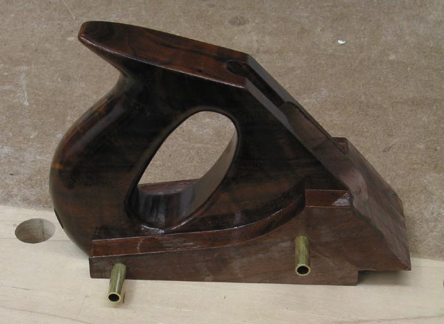
You can not rely on your infill wood not to shrink sideways,
therefore infill rivets should have metal sleeves around them to
help the lever cap hold the sides square and parallel when the wood
shrinks. (Some people disagree with the need for this extra work.)
This involves an extra step after drilling for the cross pins: you
then must remove the infill and open the holes up to the liners'
outer diameter. A useful gadget is a piloted counterbore, in my
case a 1/4" bore and a (removable) 3/16" pilot. It is useful
because you want the enlarged bore hole to be exactly concentric
with the one that's already there. Cut the liners to the exact
inner width of the shell, then press them in. This should be a very
snug fit. I applied the finish before final installation of the
infill.
 |
 |
 |
 |
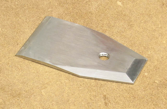
The iron was made from D2 tool steel, which proved to be a bear to machine. I roughed out the blank by using a hacksaw, line drilling and filing (ruining several files), then milling with a TiAlN-coated end mill using a very slow feed rate. It took forever to grind the bevel. D2 is an air-hardening steel which must be heated to roughly the same temperature as A2, so I couldn't do it myself with a torch. It claims to have very high abrasion resistance due to high chromium content, but some people think that it can never take as keen an edge as O1 or A2 steel.
The back iron was made from 1/8" cold-rolled steel. I roughed out the upper end with hacksaw and files, bent the lower end then ground the top down to a sharp edge and filed it smooth.
I got a question via email, and thought it might be of general interest, so I'll put the info here also.
> . . . is your back iron bent like a bailey chipbreaker? How did you do so if it is?
The back iron has only a slight downward bend--just a long gentle arch, not a double bend like Baileys. I held it in a vise with about an inch (of the eventual lower end) protruding above the jaws, exactly square, and bashed on the top with a hammer, trying to keep it to an even (left to right) amount of curl. When it was bent about 1/8" or 1/4", I stopped, then ground the top down in a gentle curve to meet the bottom surface at a knife edge. The front of the lower surface should be filed and lapped and the front of the top polished, just like you need to do on a Bailey style plane.
I believe this procedure is what Kingshott describes in his book, but I don't actually remember.
Jim
The upper tapers were ground then filed and polished.
 |
 |
With the iron, adjuster (if you're using one), and lever cap installed, it's time to flatten the sole, and only after that step should you open the mouth for the iron to pass through. It helps to have a thin file (such as an 8" warding file) and safe-side and safe-edge files to control where the filing takes place. A very tight mouth, say .005 or less, will give the best surface, but will cut slowly and has more of a tendency to clog. I prefer it this way--I can always reach for a Bailey for general planing with a more aggressive cut when tearout isn't such a concern. Don't think that historically all infill planes had tight mouths; many did not. And many were filed opened to get around the above problems. You decide.
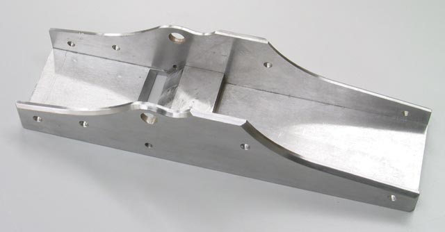
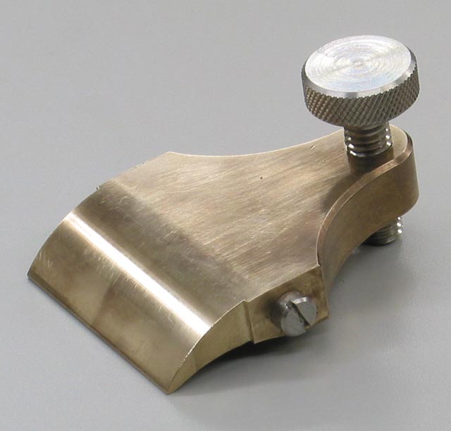
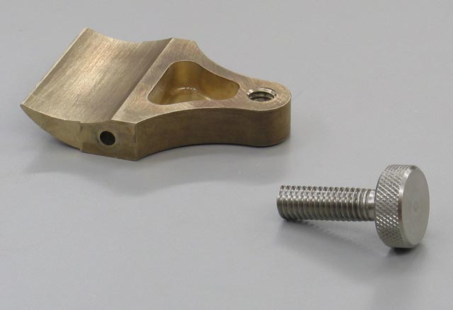
I milled my lever cap from solid aluminum bronze. This involves
moving a lot of metal, and many milling operations. Since castings
are available, I will probably go that route next time. The hollow
at the upper end of the lever cap's underside isn't necessary, but
I was starting to get concerned that the plane would turn out too
heavy when I was making this part. The fear proved unfounded. I
chose to make the lever cap removable. It pivots on the heads of
shoulder screws which are screwed into tapped counterbored holes
in the lever cap's sides. If you choose to pivot your lever cap
on a solid pin which runs the full width of the plane, make a
relief in the underside of the lever cap as I did, but extend it
forward to include the pivot hole. The reason for this is to
prevent the long bore from wandering off axis as you drill it.
(Or, if you must leave it solid, make the pivot bore first, then
machine the rest of the lever cap in reference to it.)
 |
 |
This is really an optional part, especially for a tight-mouthed
smoothing plane whose usable range of cut depth is quite small.
Chances are you'll leave the iron set in one position most of the
time. If you omit the adjuster, the mortise in the tote need be
only large enough for the screw which holds the iron and the back
iron together, open toward the top rear. You can also place the
forward rivet which affixes the rear infill farther forward, but leave
about a half inch of wood at minimum between it and the bed. Also
consider adding a strike button, low on the rear of the tote, which
protrudes slightly from flush. It should be of dense wood, about
3/8" diameter, with end-grain presented to the hammer's contact
point. Alternatively, you could put a strike button atop the knob,
but I think that such a position may be uncomfortable in use.
 |
 |
 |
 |
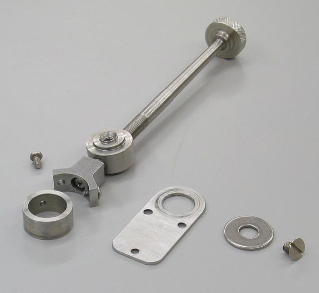
My adjuster design is a bit different from others I've seen. It has a fine-pitch single threaded (1/4-40) stem, and the "banjo" or "traveler" is made of two pieces. One reason for this is to avoid drilling a large hole in the opposite wall of the traveller to allow passage of the screw that attaches the traveller onto the stem. (Make sure you apply Loctite to this screw before installing it.) This design has the disadvantage that there's a fairly large span between the pivot and the traveler, reducing the amount of leverage you have when making lateral adjustments. A lot of adjusters are double-threaded (i.e. the stem has inner and outer threads, either left- and right-handed, or of differing pitches). I thought that my design would be simpler, but it didn't really turn out that way: it was tricky to get the traveler yoke made and fitted precisely, and there's the possibility of its affixing screw working loose.
The bed (metal and wood portions) must be one even surface, to provide solid bedding for your iron. The lever cap should meet the back iron gap-free. The back iron needs to be in gap-free contact with the iron so that wood chips don't jam. This may require filing or lapping the lower end to a sharp edge. The mouth should be filed for a consistent opening in front of the iron, with a gap you choose for the desired function of the plane, as I mentioned above. Leave it small at first, and see if you like how it works, before filing it open more. File and lap the sides perpendicular to the sole, and lap the sole to its final finish with the iron in place, tightened but retracted.
What would I do differently? Probably buy an adjuster and lever cap. Make the iron shorter, and the adjuster stem. Shim the sides when peening to avoid springback. And document less. Sheesh, all this writing took me more time than building the plane!