These milling maching programs use the CNC language of the Anilam 1100 three-axis control. Its "conversational" program files have a .m extension. The mapping from this language to G-codes is generally obvious, so a translation to G-codes should be easy, if that's what you need.
I caution those who would use these programs to review all aspects of the machining before proceeding. CNC programs such as these cannot take into account all aspects of making a part. Important variables include fixturing the part to clear all tool paths, and cutting speeds and feeds. I tried to set the feed rates so that running at 100% won't burn anything up. (This control has a 0-120% feedrate knob which can be adjusted during the run, and I'm constantly fiddling with it.) In any case, it's wise to make test runs with the Z axis set high enough to clear everything, then test parts in wood, especially of the dovetails for fit-testing. You will note that I needed to tighten up the dovetails by five or six thousandths before cutting the parts.
| Part | Portion | CNC program | Tool |
|---|---|---|---|
| Sole | left edge pins | psole-l1.m (HTML or text) |
3/8" end mill |
| Sole | left edge pins | psole-l2.m (HTML or text) |
1/2" 60° dovetail † |
| Sole | right edge pins | psole-r1.m (HTML or text) |
3/8" end mill |
| Sole | right edge pins | psole-r2.m (HTML or text) |
1/2" 60° dovetail † |
| Each Side | bottom (dovetails) | psidedn1.m (HTML or text) |
1/2" end mill |
| Each Side | bottom (dovetails) | psidedn2.m (HTML or text) |
1/2" 60° dovetail † |
| Each Side (optional) |
bottom (unpeened portion removal) | psidedn3.m (HTML or text) |
1/2" end mill |
| psidedn4.m (HTML or text) |
3/8" to 3/4" 45° chamfer mill | ||
| Left side | top profile or chamfer, rear | PLSIDUP1.M (HTML or text) |
1/2" end mill or 3/4" 45° chamfer mill ‡ |
| top profile, mid | PLSIDUP2.M (HTML or text) |
1/2" end mill | |
| top profile or chamfer, front | PLSIDUP3.M (HTML or text) |
1/2" end mill or 3/4" 45° chamfer mill † |
|
| Right side | top profile or chamfer, rear | PRSIDUP1.M (HTML or text) |
1/2" end mill or 3/4" 45° chamfer mill ‡ |
| top profile, mid | PRSIDUP2.M (HTML or text) |
1/2" end mill | |
| top profile or chamfer, front | PRSIDUP3.M (HTML or text) |
1/2" end mill or 3/4" 45° chamfer mill ‡ |
Note: PDF prints may not be as accurate as the original CAD files, which you can download.
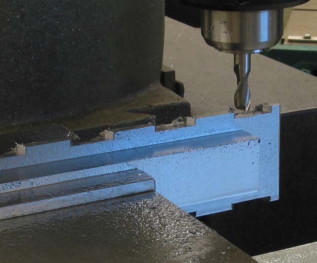
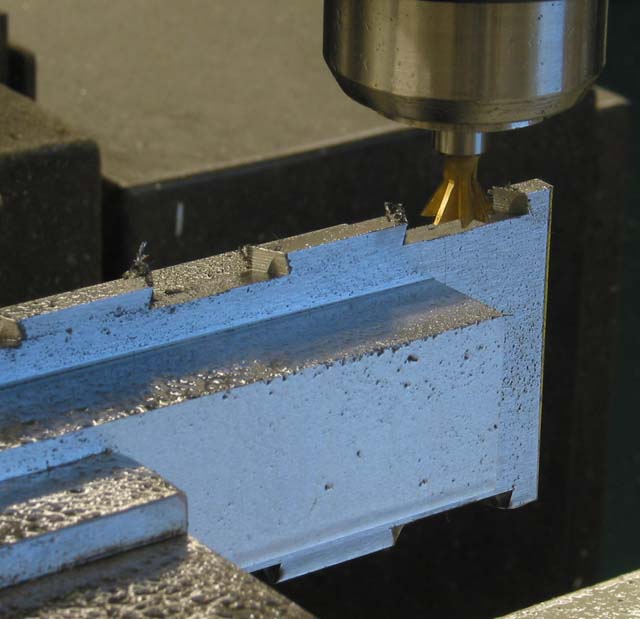
| The sole is machined in two passes. First, most of the metal between the pins is hogged out using a straight end mill, to full depth (see CNC programs PSOLE-L1.M and PSOLE-R1.M for the right and left edges, respectively). Then the secondary bevel's parabolic void is made using a dovetail cutter (see CNC programs psole-l2.m and psole-r2.m). | |
|
|
|
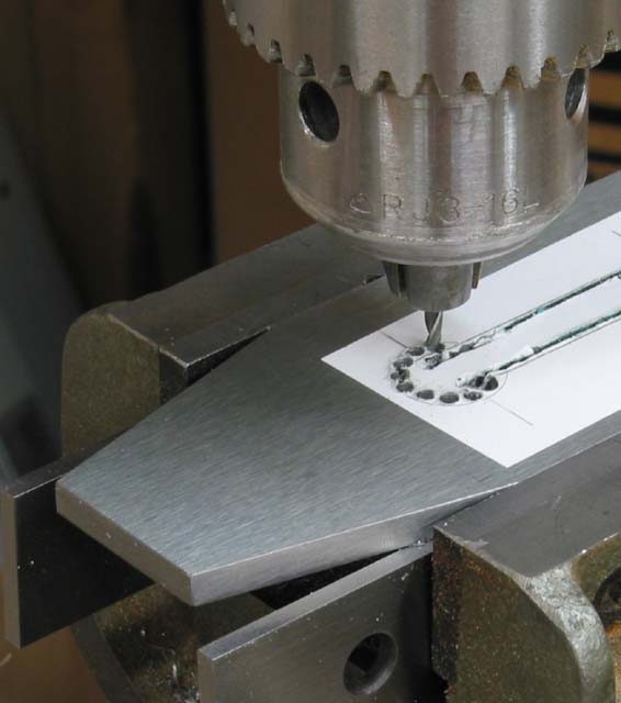
| After making the pins on the edges of the sole, make the slot through which the iron passes, and rivet the throat plate on. I line-drilled and filed the slot, since slot-milling with small end mills is so slow. It also saves time to rough-cut the bed angle, and maybe even tune the bed's surface, on the thoat plate's front before riveting. Further refine the iron's bedding surface after the throat plate is attached, continuing all the way through the sole. Also cut the angle in front of the slot to form the chip escapement, again cutting full depth through the sole. I used a bed angle of 45°, allowing the same tilting vise setup for the angled cuts on both the front and the rear of the slot. [n.b. It is wise to leave the bed-angle setup identical when milling the bed on the metal sole and on the wooden rear infill.] | |
|
|
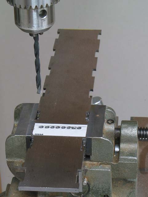
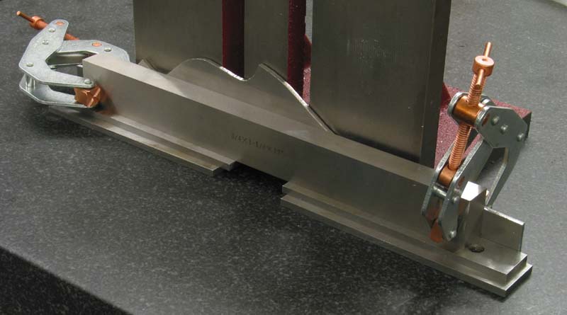
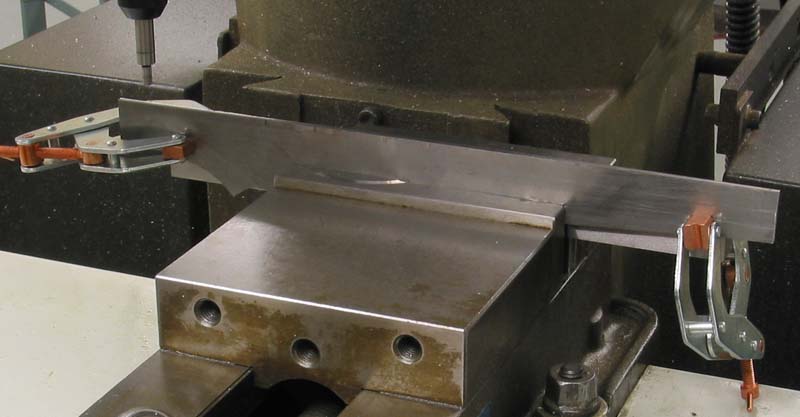
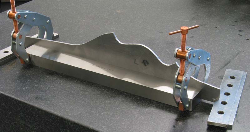
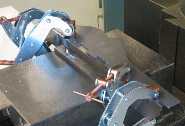
When fixturing the sides you need to have them held in the milling vise upside-down, so that the curvaceous profile is down, leaving nothing flat and parallel to the part's lower edge to bear on the vise's base. I got around this by clamping the part to a precision-milled bar (3/4 x 1 x 12), leaving the lower edge of the side protruding enough to clear the clamped bar when the final milling pass at final depth is made. (This is 3/16" sole thickness plus .050 more for peening stock.) The photos show how I used stacked parallels to space this protrusion and maintain parallelism.
|
|
|
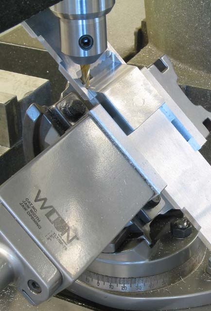
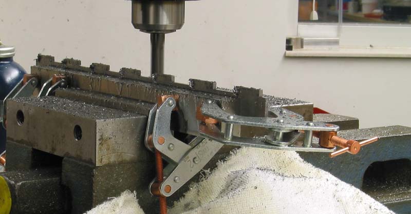
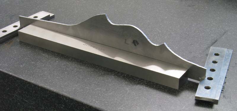
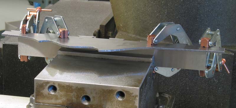
Holding the sides for milling the upper profile provides similar challenges. The next three photos show how I set up the left side for cutting the profile and chamfers. (Rough-cut the profile first using a bandsaw or jigsaw.)
|
|
|
|
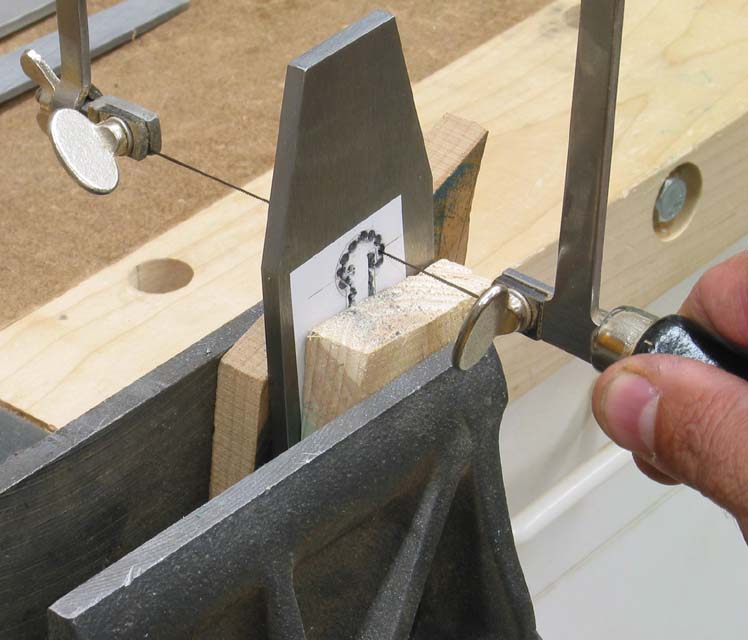
I used a hacksaw, drill press, jeweler's saw and files to make the iron from O1 tool steel, then heat-treated it with an oxy-acetylene torch, quenched in oil, then tempered with the torch again.
|
|