
As received from Arno, these TB's were shorter than I had expected. I want to keep the intake track as long as possible to keep the torque curve high at intermediate RPM's (2000-5000). Originally I had planned on modifying the Burton Power intake manifold by adding bungs for the fuel injectors but to keep the intakes long, I decided to use part of the stock Ford Focus intake manifold.
I cut off the section that mounts to the engine and holds the injectors. This is about 1.25" long. I matched the ports on the Burton manifold and the Focus manifold to the intake ports on the head and sealed the focus manifold ports. Then the Focus manifold was sandwiched between the Burton manifold and the Zetec head and bolted together. I used Weber o-ring gaskets to mount the new DIY (Do It Yourself) TB's to the manifold - not because I wanted to isolate the TB's from the motor as is normally done with Webers, but just because they were handy.
I tried to purchase a top pull or bottom pull throttle linkage for the TB's but no one had anything that would work with these DIY TB's. So I build my own throttle cable mount using one from a Ford Focus. I also used the Focus throttle cable (see picture above).
With the TB's mounted I started on rewiring the car for the Emerald ECU. I removed the Ford ECU & wiring. The Emerald ECU is smaller than the Ford unit so I mounted it above the drivers left knee. The wiring goes from the Emerald, under the heater fan where a little over half of the wire exit the cabin to through the transmission tunnel to the engine compartment.
I added four relays for the Emerald system. A Run Relay; A Fuel Pump Relay; A Coolant Relay; An O2 Heater Relay and a 6-way fuse block (see wiring diagram). The theory is that the Emerald will turn on the Run Relay when the key is operated with makes energizes the fuse block. The Emerald then runs activates the Fuel (which turns off after 5 seconds if the engine does not start). With the engine running and the Fuel Pump Relay energized, the Coolant Relay and the O2 Heater Relay are powered and will activate under control of the Emerald ECU.
The Coolant Relay will turn on the radiator fan by shorting across the Birkin thermo switch. This is under ECU control, so I can decide at what temperature the fan turns on and off (90C on and 85C off) when the engine is running. If the engine is off, the fan can still run under control of the Birkin thermo switch (turns on at 100C).
The O2 Heater Relay is also controlled by the ECU. Any time the engine is one, the ECU can turn on the O2 Heater Relay. However, if the engine is not running, the ECU can not turn on the O2 Heater.
I also added a BARO sensor under the TB's. Where I live, in 30 minutes I can go from 4200 Feet above sea level to 9000ft above sea level and in 8-10 hours I can be at sea level. Hopefully the BARO sensor will keep everything at optimum operating efficiency regardless of Altitude.
I've also added a cigarette lighter that is mounted near the passenger's right knee.
Future additions will be a oil waring LED and a bright white shift light.
Currently, the engine starts and runs and idles at 980 RPM's. With the switch to the DIY TB's, I upgraded the injectors from the stock 18lb/hr (192cc/min) to 24lb/hr (256cc/min) Ford Performance injectors. The original injectors were good for about 135HP at an 85-90% duty cycle. The new injectors are good for 180HP at a 90% duty cycle.
Next project will be to get the mapping correct for this engine in this car with these TB's, injectors and the Birkin exhaust. Initially I will be using a map from a similar setup thanks to Keith Banthorpe.
More to come!!!
 I tired to use as much as possible from the original 2001 Focus harness. I initially tried to use the 2001 Focus computer, but the PAT (Passive Anti-Thieft) features of this ECU were not easily defeated. Steve is currently looking into the possibilities of using this computer in the future.
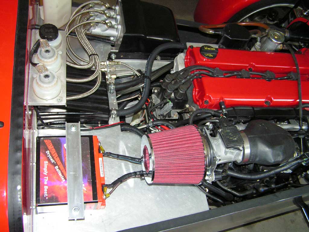 In this picture you can see the new K&N style air filter and filter adaptor that connects to the Birkin Sport 90 degree intake. When trimmed this rubber unit will just clear the hood (or Bonnet).
 From the drivers side you can see how clean the engine compartment is using the center tunnel for routing the wiring harness. In the future, I may replace the Ford ECU with an Emerald unit to allow a greater range of ignition and injection fine tuning.
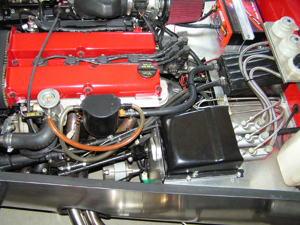
From this side of the engine you can see the Birkin furnished coolant recovery bottle. You can also see the Focus throttle cable that was shortened for use in the Birkin. The Birkin throttle assembly allows you to adjust a throttle stop at the throttle pedal. I does not allow you to adjust a closed stop. I added a closed throttle stop and adjusted the full throttle stop to allow the throttle to fully open the throttle body without putting excessive tension on the throttle cable. (See engine photos for the throttle stop).
Hiding in the lower center of the picture you can just see the white and green O2 sensor connection.