I'm a software guy, and many parts of this are a hardware problem. This is presented as "What I did", not "How to do it". I can't say this is the best way, or even a good way. It does seem to be working so far. Scroll down to the bottom to skip the story and get to the tech details. Click on any picture to get full size image.
I've wanted an AOA in my airplane since reading Aerodynamics for Naval Aviators back in the 90s. This is my third try, I'm pretty happy with it.
This is inspired by the FlyOnSpeed user interface. I wanted to build one of those, but the parts were never available. Rather than try to reverse engineer theirs enough to get it to work with a different chip, I decided to make my own.
Because I have past experience with the Raspberry Pi, went with that hardware instead of arduino. There are lots of available modules to handle the hardware end of things that I don't know how to design, so I can just buy parts and hook them up.
The OnSpeed design uses two 14psi differential sensors, I tried that at first, but 14psi corresponds to about mach 1, much faster than my RV-8A. This large range means that the lower end where I would actually be flying has lower resolution. The lowest I was able to get reasonable data was around 50mph, which is only just below my below my stall speed. I instead used a sensor with +/- 1.45 psi range which means it can handle up to 280 KCAS or so. (Speed calculation from NASA 1046 Measurement of Aircraft Speed and Altitude)
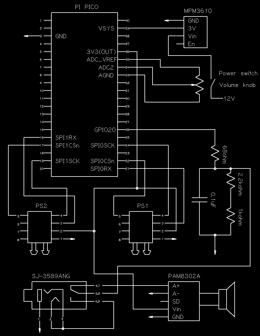
Used the PWM circuit on the pi to generate audio, then run it through a simple filter to remove the high PWM frequency. Sampling the pressure sensors around 2,000 times per second, faster than that resulted in the "stale data" errors. Average 200 values to even out sensor noise resulting in updating my tones 10 times per second.
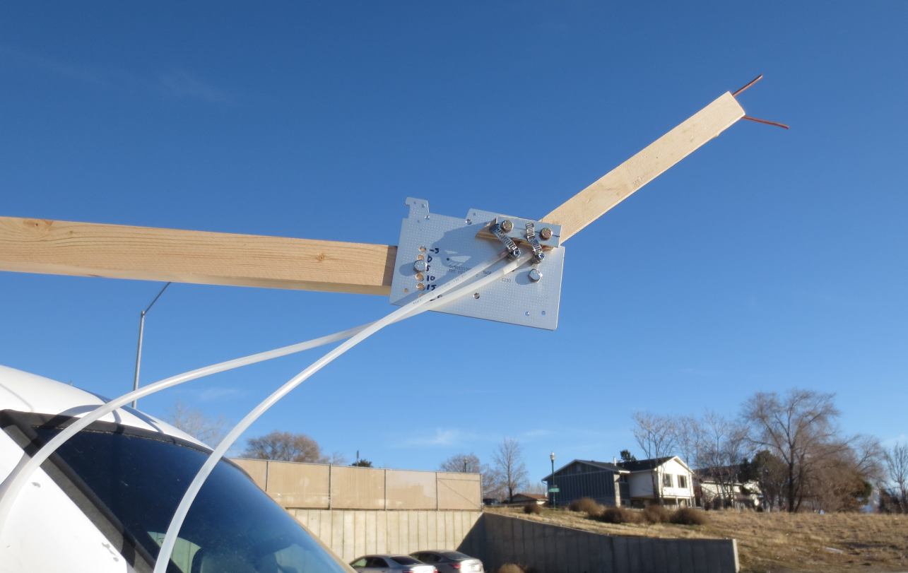
I first set it up to just log the pressure difference readings from a probe mounted to a stick in front of my truck. Out in front of the windshield to hopefully get in front of the truck's turbulence. It was these tests that convinced me to use a more sensitive sensor.
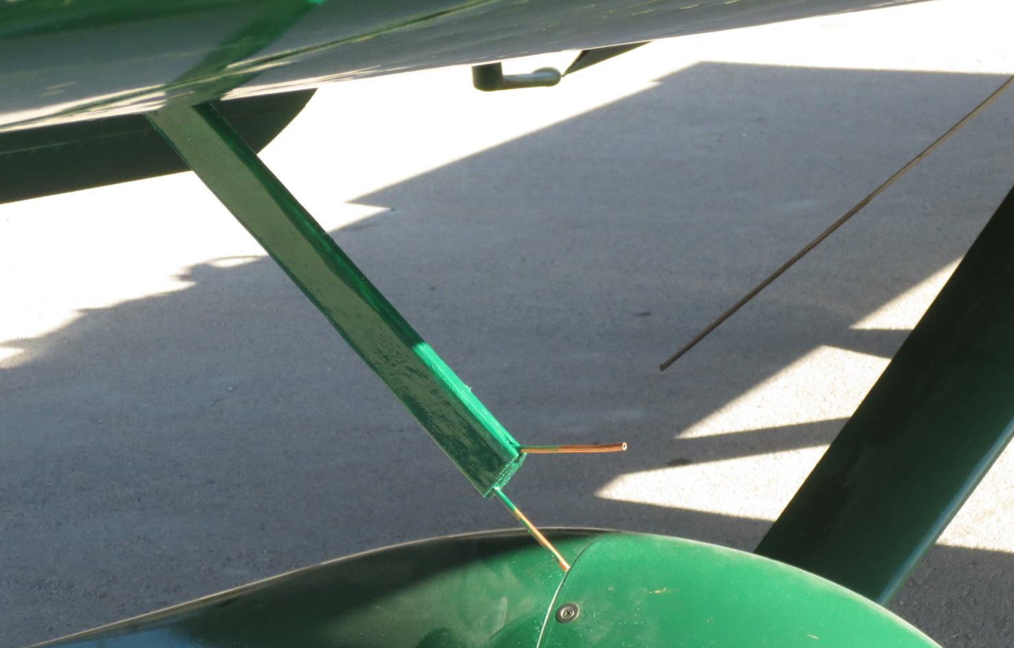
For the probe I used 1/8" OD copper tubing I had left over from making the engine priming system. Cheaper than buying new 1/4" aluminum tubing. I routed a space for the tubing in two thin boards, glued the boards together and then spoke shaved them into a rough airfoil. This was then attached to an inspection plate cover (got a new one from Vans). I put it in the 2nd outboard position to have it be outside of direct prop blast. Seems to be enough, a full rudder slip doesn't appear to hit it.
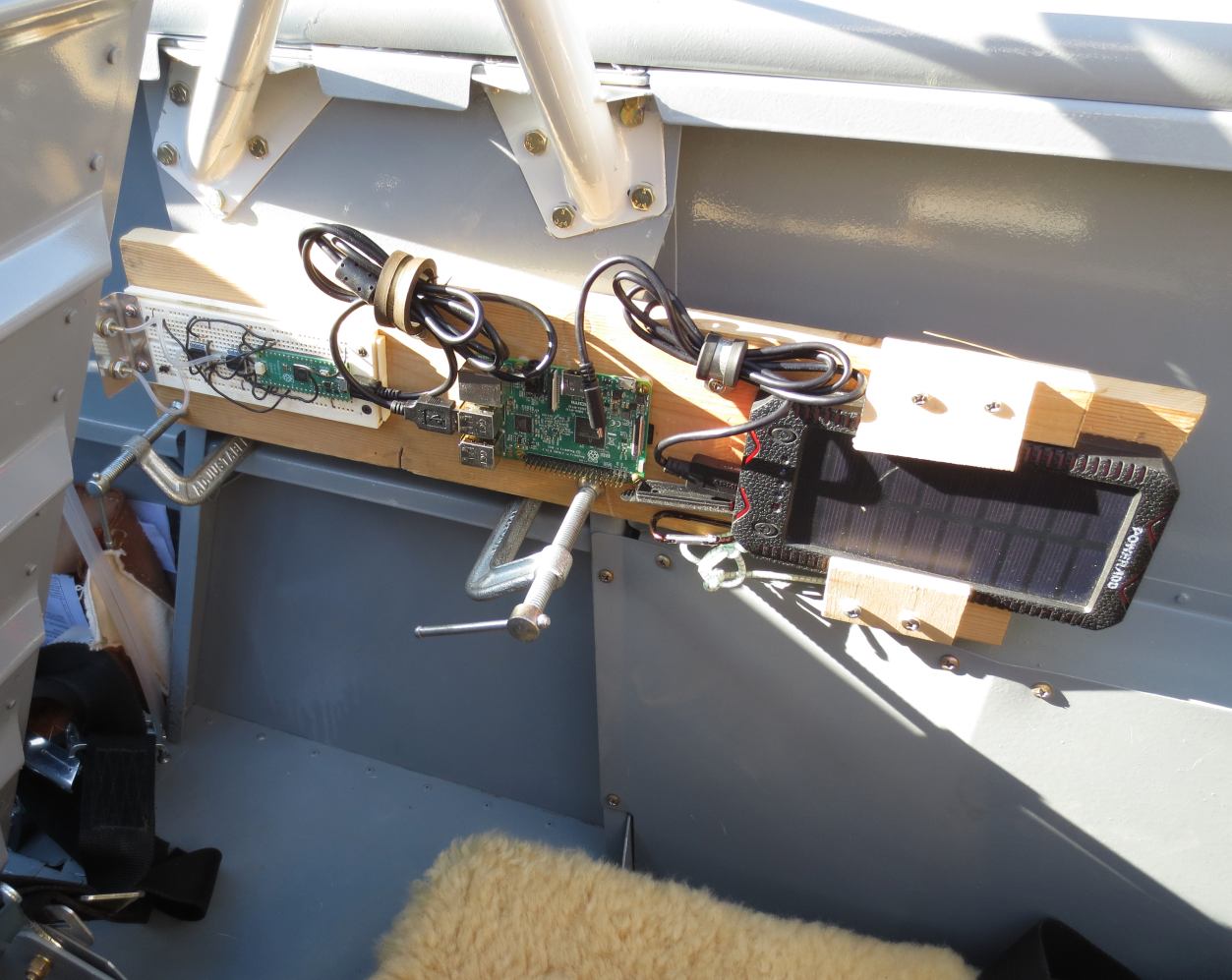
Using a Raspberry Pi as a logger with a portable USB power source, just c-clamped it into the cockpit to get some data for initial calibration. Fly many power on, power off, accelerated, flaps up and flaps down stalls as well as just spend time at different speeds.
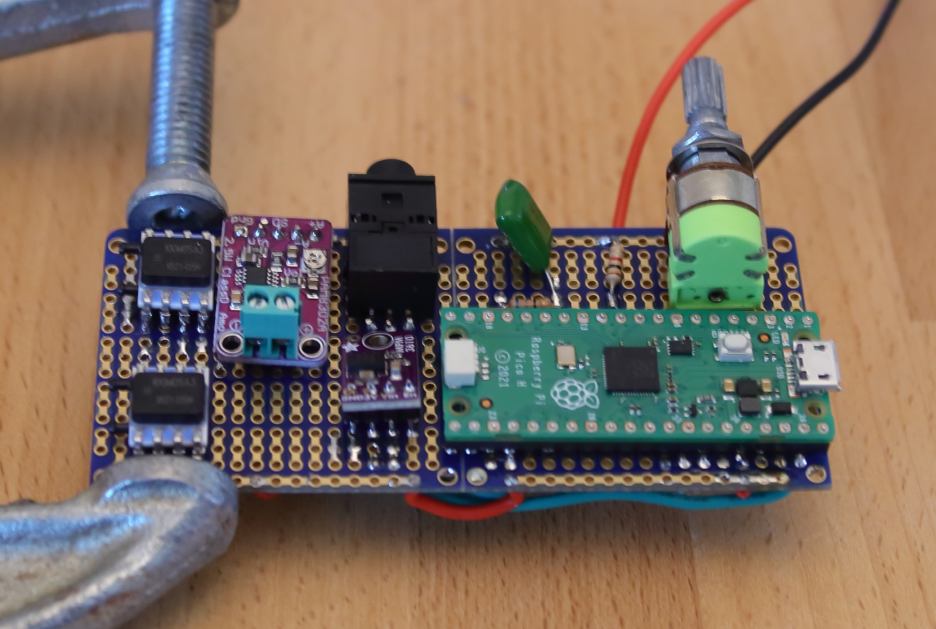
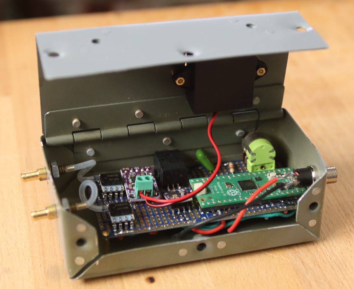
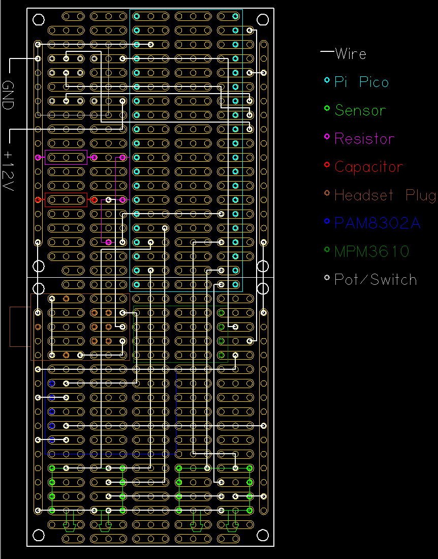
Satisfied with getting the data, I move on to making actual flight hardware. Find some breadboard PCB boards, and a small speaker. Been a long time since I've done this much soldering, but get it together.
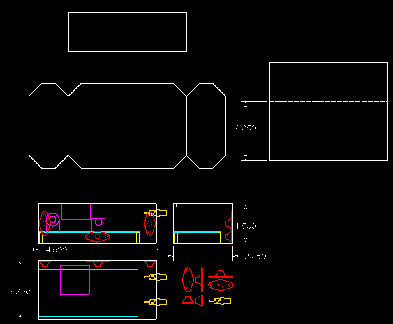
Trying to find an enclosure to hold it all together, I don't like what I can find online. Everything is too big for my minimal needs. Buy one to try, but don't like it when I get it. Decide to make my own out of sheet aluminum which I have plenty of. Use brass standoffs to hold the board into the case. As I am just using the cabin interior for my static reference, I don't want the enclosure to be air tight. Leaving big gaps actual helps the design.
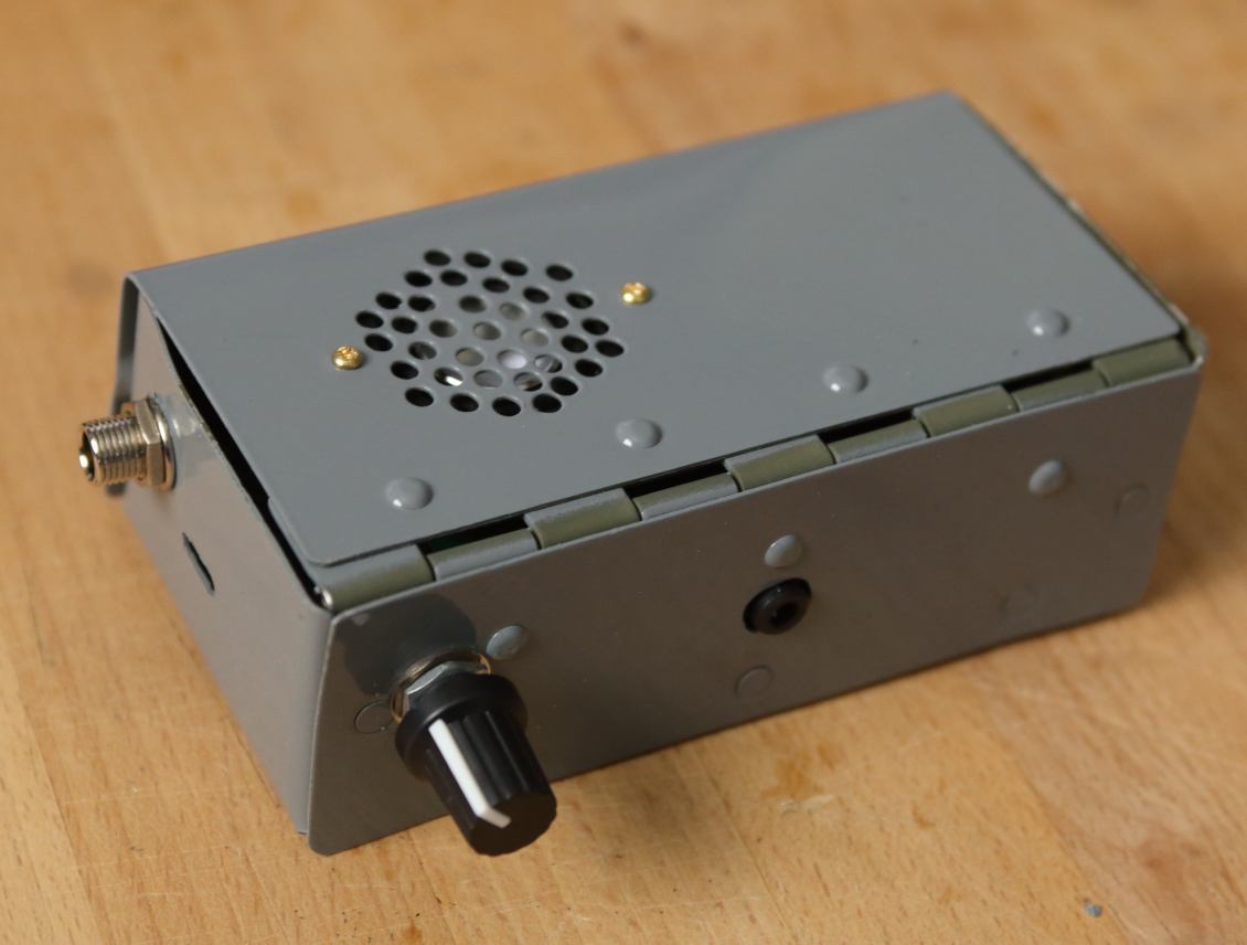
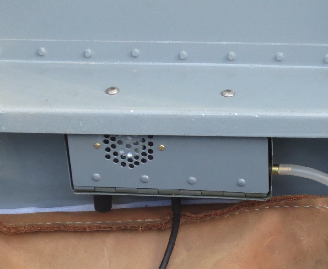
The case then installs under the "armrest" fuselage side with two screws. Fits above my leather map/document bag. Just two holes in the armrest into nutplates in the enclosure. I can reach the volume knob/switch and headset plug easily from the seat.
Time to use in flight, I hadn't had all the parts together in the plane until now. Find I can just barely hear the tones in flight. Speaker is only audible if the engine is at idle. I was using an "impedance matching" circuit I found online, it is dropping the output voltage from 3v to around 1v. I change where in the circuit I am taking the output (keeping the high frequency filter in place).
After that change I can hear the tones fine using the "music in" plug on my ANR headsets, but still not loud enough from the speaker. The speaker was always only the backup option, so I'm calling it good enough.
Takes a few flights to get the calibration correct. After that it does do everything an AOA should do. Correctly predicts stalls, allows for very precise "eyes outside" approach and landing.
| Part | Use |
|---|---|
| Raspberry Pi Pico | Main Processor |
| MPM3610 | Power Supply |
| Honeywell HSCDRRN100MDSA3 | Differential Pressure Sensor |
| PAM8302 | Audio Amplifier |
| PCB Board | Board |
| JST-PH2.0 | Speaker |
| Uxcell Pot/switch | Potentiometer with switch |
| Brass standoffs | Standoffs and screws |
| 1/16" ID tubing | 1/16" ID tubing for sensor |
| 5.55x2.5mm DC plug | Power Plug |
| SJ-3589ANG | Audio Plug |
| CL170822BR | Knob |
Also some wire, resistors and capacitors which I had from an old set I inherited. I couldn't find a bulkhead fitting/tubing size adaptor to go from the 1/4" tubing in the wing to the 1/16" the sensor needs so I turned that down from brass rod.
All told added 0.7 lbs to my plane. Testing showed a max power draw of 61ma, when playing tones to the speaker.
The source code can be downloaded here:
source.zipIf you are going to try to replicate what I did, you will need to change these lines:
#define MINPRES 0.0053  //below this pressure, data not reliable
#define LOWRATIO 1.30  // stall aoa ratio
#define MIDRATIO1 1.60  // on speed ratio low
#define MIDRATIO2 1.62  // on speed ratio high
#define HIGHRATIO 2.00   // best glide ratio
These are the values that worked for me, but unless you exactly replicate my airplane and probe your values will be different. To be able to get the values to calculate the code writes to the USB port a timestamp and the pressure readings it gets. If you set up something to record that output and video a flight it is easy to match the timestamps to the video to know what pressures correspond to what flight behaviour.
It works by calculating the ratio between the straight ahead and 45° down tubes from the probe. These are differential pressures with the "static" pressure. For static I used the inside of the cockpit, this obviously wouldn't work with a pressurized plane.
These lines may need to be changed if your potentiometer works out different from mine
#define VOLLOW 29  // low volume
#define VOLHIGH 1  // high volume
The primary motivation was to build it with hardware I could actually get, but I also intentionally aimed for something simpler. No display, no accelerometer, no recorded voice messages.
One thing I am missing that would be better to have is a flap position input. My old 1990's flap motor doesn't have a position output, I thought I would try without it first and only add if needed. So far I don't think I need it. The flaps down stall is only a little bit deeper into the continuous tone, close enough for my purposes.
The speaker didn't work out. Annoyingly loud on the bench in a quiet office wasn't enough to be audible over engine noise. Would need a much more powerful amp and speaker. So, I would just leave it off. Put a small hole in the enclosure so I could press the reset button with a toothpick and load new code/calibration while still in the plane.