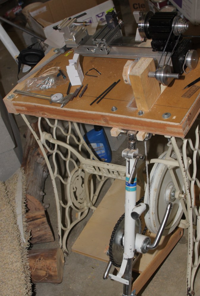 From the back, showing the crankset and mounting.
I've wanted a lathe for quite some time, and after three projects required working around the lack, decided to actually do it. After many years of watching Roy I knew that I wanted it to be treadle powered. Also, my turning needs were more for smaller machine parts than furniture legs.
There used to be such a thing as treadle metalworking lathe, but nobody has made one for 100 years, what with electricity being cheap and universally available. I find antiques for sale online, but not at prices I could afford, and nothing around here. There are lots of homebuilt lathe options. You can go with cast aluminum, concrete, or bolted pipe and angle. But it is difficult to make a solid headstock, and keep the ways parallel. I have too many other projects going to start from scratch on this one.
There are always the Chinese lathes, I read that they work pretty good, but you need to completely disassemble them and take out burs, then reassemble and align everything first. I've been drooling over the Taig lathe in the Lee Valley Catalog for a long time.
The Taig is pretty much universally reviewed as very accurate right out of the box. They also say it is very small, and can't thread without getting clever. However, and very importantly for my purposes, it is sold separately from the motor, and is designed to make using different power sources easy. Small may even be good given limited power available. It is designed for a 1/8-1/10 hp motor, and athletes can put out up to 1/4 hp. I should be good for 1/8-1/10.
In the shed back of my previous house, there was a treadle sewing machine base, I've been keeping it to make into a treadle lathe stand for about 10 years now. It has just the base, no treadle or flywheel. So I need to come up with all of those parts.
The sewing machine used a 12 inch iron wheel, but remembering that moment of inertia varies with the square of radius, I think about using a 20-24 inch wooden one. It will be tricky coming up with a way to mount it in the frame. While I'm thinking about that, I find an exercise bike on Craigslist for $10. It has a 12 inch iron flywheel. That will have the same moment as a 20 inch wooden wheel, and should fit in the frame.
Mounting the wheel proves to be a bit trickey. I have the mount screw for the sewing machine wheel, it is an obsolete 1/2"x16tpi thread, going to a tapered end that the wheel is supposed to rotate on. For a few months, I think about how to do this, but everything I come up with would take a screw cutting lathe to match that old thread, or boring out the hole making it so it can't be sold if this project doesn't work out.
Then one day it occurs to me. Drill a hole in the end of a bolt to match the screw, and then taper the other end to fit the receiving end of the sewing machine crankshaft. The wheel has decent bearings, so the shaft doesn't need to move. I can use the bicycle gear already mounted on it to drive. It was on a 10mm shaft, and I have plenty of 3/8" bolts to use. About 15 minutes to drill the hole and taper the end on the grinder and the wheel is mounted.
As the gear is mounted on a freewheel it will only let the wheel turn one direction. The wheel only fits in the frame one way (and barely at that), so I can't get it to turn the way I want. I want the wheel on the left side, as lathes are driven from the left where sewing machines are on the right. The frame is made out of symmetrical castings, so I can swap the frame to the other direction, but the wheel will be rotating the wrong way. I will need to let the belt cross over. More belt wear, but greater friction area on the pulley.
Swapping the frame over turns out to be tough, the screws are painted over and have been rusting in place for 100 years or so. Lots of oil and a bit of heat gets them loose. I run some bike chain over the gear and to a spring. That and a small torsion box treadle can get the wheel going pretty good, if not quite as fast as I want.
I build a table out of scrap 2x and some plywood, with a solid area where the lathe will attach. In so doing, I accidentally put a stiffening board where my belt hole was supposed to go. I end up having to shift the table over 1.5 inches, and make a very thin side to the mortise to hold the pulley shaft board. Making the pulley is a bit of a challenge, using my drill press like the lathe I don't yet have. It mostly works, but the string I am using as a belt falls off alot. I decide I am far enough along to purchase the lathe using a bonus I got back in January (yes, waited about a year).
Order from a2z as they have the best price I can find, makes sense not to ship it back and forth to Canada. I get the "power feed" option, thinking I may be a bit shakey while I treadle away. Takes about 3 weeks to arrive.
In keeping with the cliche that home machine shops are mostly used to make parts for home machine shops, the first thing I set out to make is a better pulley. I sew up a leather belt out of scraps, works way better then the string. I get started on the pulley, but it is clear I need to get it to go faster. I had suspected this would be the case, so have been thinking about how to mount the pedal/chainring.
I come up with a way, using the handlebar mount from the exercise bike, tap and drill the pedal about half way down. It is the hardest thing I have ever tapped. Takes about 2 hours to tap the hole, but I get it done without breaking my tap. Cut an arm out of scrap hardwood, and attach it to the treadle. One pump, the treadle goes to the floor and stops. The wheel is moving nicely, but the freewheel doesn't let the treadle come back up for the next stroke.
Search around online for a while, and finally go to the local fixie bike shop and get a fixed 12 tooth gear, the smallest they have. With that, I have about 4:1 on from the chainring to the pulley, then 6:1 from the wheel to the pulley, giving a 24:1 speed for the shaft. Make getting up to the 1750rpm the lathe is designed for with an easy 73 rpm on the treadle. This works Ok, but the force from the treadle is rotating the crankset around the shaft. I end up drilling and tapping a screw to hold it in the right place. Also make an arm to hold the shaft out at the right angle.
Now its working quite well. However, the one-sided treadle I made for the chain-spring option means you only push half of the time, and you are pushing the lathe away from you. I end up having to hold the frame with one hand while working the lathe with the other. With the extra speed, when the belt falls off it gets into the chain and then is cut by the gears. After the second time just go to cheap nylon rope, will make a leather belt once it stops falling off.
Make another longer two sided treadle, also a torsion box, for the stiffness. Makes it very easy to get up to speed and keep it going, especially with the straight down push on the near side.
After getting the new pulley done, the rope doesn't fall off anymore, so I machine a spacer to keep the shaft in the right place. Easy to bore it out to just over 1/2", and sneak up on the right length.
That's how far it is in these pictures. I will next replace the 2x4 pulley mount board with some hardwood, as the soft pine is already compressed, messing up shaft alignment. I might replace the vertical shaft with something hinged to allow for the wheel belt to be loosened when not in use.
In keeping with my making things with garbage recycling ethos, I tried to do as much as
possible with scrap I had laying around. So far spent about $20 on the base, table and
treadle (the lathe and accessories
came out around $500). I needed to buy some bolts in the right length, as well as a 1/2" shaft.
Only really had it working a week, but pretty happy so far. Even tried making an
airplane part,
but cut 1/16" of the radius instead of the diameter, so it doesn't fit right. Need to do it over.
If I get tired of treading, I can always hire an apprentice get a motor. For now, I
need the exercise.
Short term planned improvements are a tool holder, spur drive for wood and a dust cover.
From the back, showing the crankset and mounting.
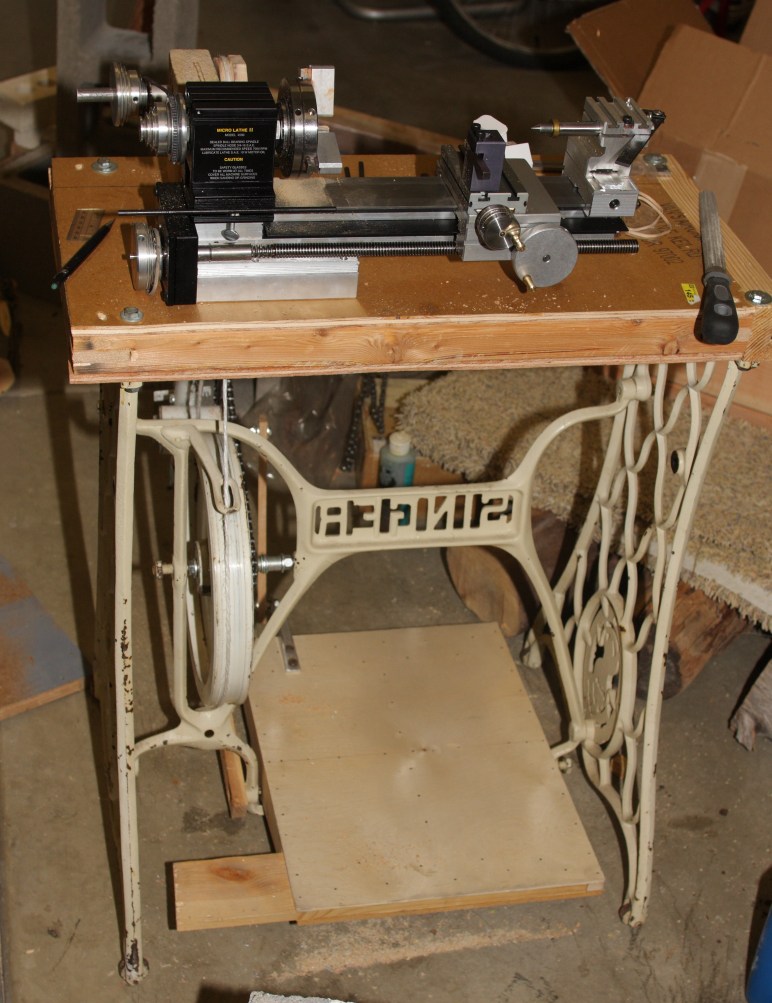 From the front, showing "SINGER" backwards, and the treadle.
 From above, showing the lathe and pulley.
 A short video showing it in action (2.6Mb).
The bearing in a 2x4 pulley mount was putting too much force on the soft wood, causing it to dent. This let the shaft get out of alignment, causing various parts to rub that should not. After a while, there wasn't enough force left over to turn the lathe. Decided to upgrade to ball bearings, and to put them farther apart so that the shaft would stay aligned.
Built a box out of 1x4, with plywood covering part of the top for stiffness. Press fit the bearings into the ends, and mount the whole thing on a hinge. This lets me lift up the box to tension the belts, and then lower it down again to take the tension off for storage.
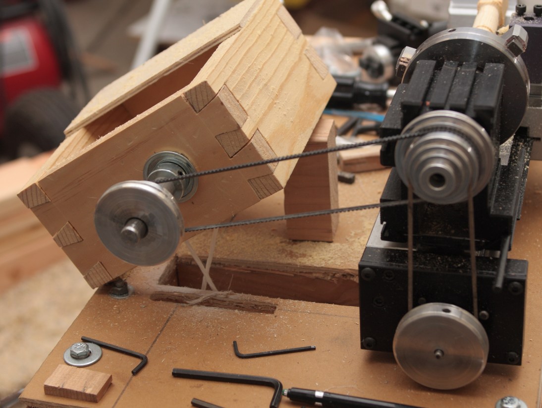 Showing the box from the side. Also showing how bad my hand-cut dovetails are.
Need to work on those, so this is good practice. Fortuitously, a scrap of 2x4 holds
the box at just the right angle to get good tension on the belts.
Showing the box from the side. Also showing how bad my hand-cut dovetails are.
Need to work on those, so this is good practice. Fortuitously, a scrap of 2x4 holds
the box at just the right angle to get good tension on the belts.
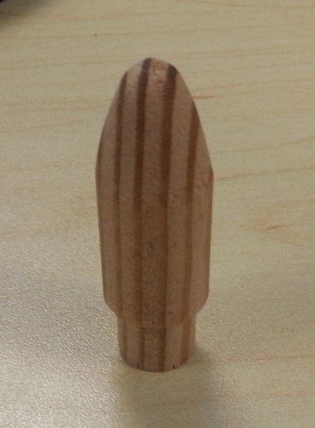
 From the front, starting on the replacement AOA mount nose piece. Also showing my home made spur
drive, which works but convinced me to pay for
a better one.
From the front, starting on the replacement AOA mount nose piece. Also showing my home made spur
drive, which works but convinced me to pay for
a better one.
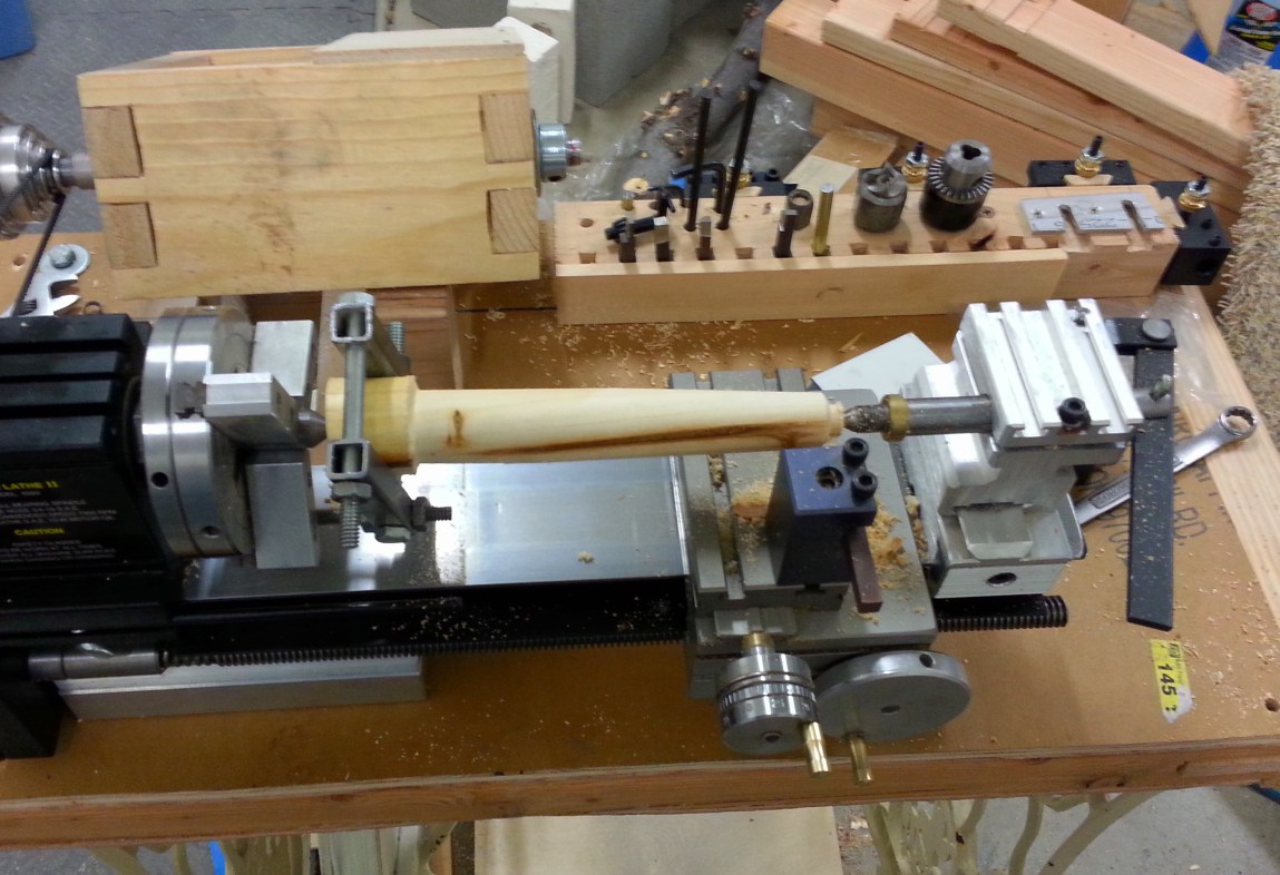
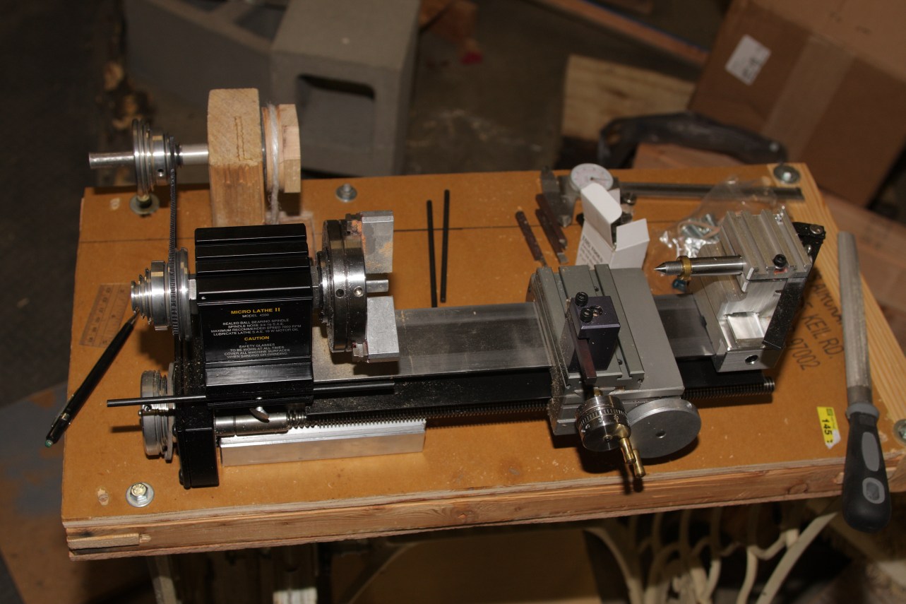
Made a tool holder so the various parts weren't just scattered on the table. Also made a lathe dog and live center so I could try some taper turning. The live center is made from scrap from the pulley axle. The lathe dog from some 1/2" square tubing I had left over from a project a few years back.