It can be built for about $20. I have produced a larger version containing a latch to disable firing until a launch event, and a smaller version without. The latching version can be hooked to a G-switch, and the pyro will be armed when the switch stays closed for about a quarter of a second. A normally-open pull-pin could be used instead, wired between pin 1 of the LM358 (the first op-amp's output) and the transistor's gate, in which case the CD4011 quad NAND chip could be omitted, along with its various timing resistors and capacitors. (These are listed as optional in the Bill of Materials.) The two points on the circuit board where you would attach pull-pin leads are marked PP on the larger PCB, i.e. pins 1 to 4 of the 4011 chip. For that matter, you could solder a solid wire there instead, and not have any launch detection at all, making it equivalent to the small board. This of course requires you to wait to arm the rocket until it's on the pad and vertical.
The Continuity LED (D1) can be soldered onto the board, providing you can see it when the rocket is ready to launch. Or, you can solder some extension leads onto the LED, mount it into the airframe wall, and run the leads to the Cont terminal block. (Lest they be too dim, don't install both.) Test your LED with R3 to make sure it's bright enough. I suppose you could install a piezoelectric buzzer instead of the LED and its series current-limiting resistor R3; the LM358 should have enough current sourcing capacity (20mA) to handle piezos I'm familier with, but watch the battery drain. I'd rather look at an LED than put up with the squealing while hooking up igniters, personally.
Follow the links below to for schematics, layout files, and a parts list.
The G-Switch can be jury-rigged using a microswitch with low activation force, weighted for the number of G's you want. I have bought small in-line units from Pefectflite for $8. The go onto the board in the "Alt G-Sw" location, so they can sit right on the board.
I'm looking into a high-temperature version, rated to 125°C. The op-amp is the hardest to substitute for a mil-spec part. Check back later.
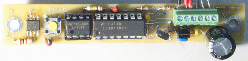
Note: the photo shows the G-switch version, without the switch installed yet, but rather a jumper wire in its place. It's easier to calibrate and test the Flux Comparator before installing the switch. Notice that there is no calibration resistor R2 (upper left) yet.
The capacitors listed as tantalum are rated 10%, 35V. If you can find wider-tolerance and lower-voltage units, they may be smaller and less expensive, or not use tantalum, which will cost less, but be generally larger, with pin spacing more than a tenth of an inch. e.g.20% tolerance ceramics: Digi-Key P4968 (1µF, 35¢), P4967 (.47µF, 17¢) have 5mm lead pitch.
Choose any N-channel power transistor you like, depending on the current requirements of your squib. The IRFD110 will pass an 8 Amp pulse; the smaller ZVN3306A can handle 3A, which should be enough for anything I can think of. You'll need to bend its little legs to fit pins 1 (gate) and 2 (source) of the DIP4 pattern, then put the drain pin into the extra hole extended down from pin 4 of Q1's DIP-pattern layout. (See the ZVN3306 data sheet for its pinouts, or the above photo.)
There are a few things you need to watch when building the circuit.
The version without a G-switch is easy to test: you just turn it over. (When you first build it, you need to hold it vertical and press the Reset button.) The pyro will trigger. You can put a light bulb or an LED and series resistor into the Pyro terminals and watch when it lights up. Adjust R2 if it doesn't trigger when you want. The desired attitude is usually horizontal. The North/South angle will be a compromise. If you installed a G switch, short-circuit it (or install it later) when calibrating R2.
Last updated: Sep 21, 2007