This isn't really a comment on your drawings, which I think are
excellent, but rather about how secondary bevels in general are
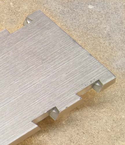
formed. The photo I posted of the secondary bevel on my sole's pins
doesn't make things as clear as I had hoped. Here's the photo. (The
orientation matches the photo: bottom of the sole is up, front toward
the right, and the drawing shows the slot for the iron which isn't
visible in the photo.)
I put together some 3D wireframe CAD drawings to try to explain. The
shape of the secondary bevel is parabolic (I think that's right: a
plane intersecting an elliptical cylinder). The outline of a
traditional (wooden) dovetail joint's pins is shown in black, and the
secondary bevel is in blue below.
It is created using a dovetail end mill, but the angle of the cutter
is 60° which would be called 30° in terms woodworkers use for
dovetail router bits. First I used a "straight bit" end mill to cut
the normal pins (black outline.) Then to cut a 75° secondary
bevel, the tip of the dovetail mill must follow a path shown by the
green full circles connected by arrows. Imagine the flutes sweeping
through the short green arcs, removing metal between them and their
corresponding short black lines. (It's easier to picture with the
dovetail cutter advancing in the opposite direction from the arrows,
but that's not how I did it, for the sake of tool wear.)
Notice that the void I created does not go all the way to the intersection where the two inner faces of sole and side meet. This has several advantages. First, a larger mating surface remains between pin and tail walls, helping keep pieces firm and aligned when peening. Second, it increases the angle of the face at which the peened tail material meets the secondary bevel void in the pin's wall, giving the joint more strength. Think about countersinking the hole for a rivet: you use a 82° or 90° countersink, not a 5° or 10° tapered reamer, allowing the hammered metal to exert much better force on the inner conical wall of the countersink. Further, there's a limit to how far you can push metal down into these voids. I haven't pulled or sawed apart any peened dovetails, but I suspect that the peened metal doesn't extend nearly to the bottom of its well.
A similar effect is available to planemakers who use files to create
their secondary bevels. Some further drawings will save me typing a
thousand words each. This drawing shows normal dovetails before
secondary bevels are filed. The sole is black, the side brown.
I have included extra stock for peening and filing in this drawing, in
different colors.
Now the edges of the filed secondary bevels are shown in brown,
similar to your illustrations posted last week, Steve.
Here is the shape of my suggested alternate filed void, which doesn't
go full depth. I'm not sure how deep it should be filed, and perhaps
people may want to weight in on this issue, especially if they've
taken apart some peened dovetails to observe the depth of the peened
stock.
Hope this is understandable. I would welcome feedback.
Jim