Building a Dovetailed Infill Panel Plane
Jim Yehle - Salt Lake City - April 2004
Design Notes
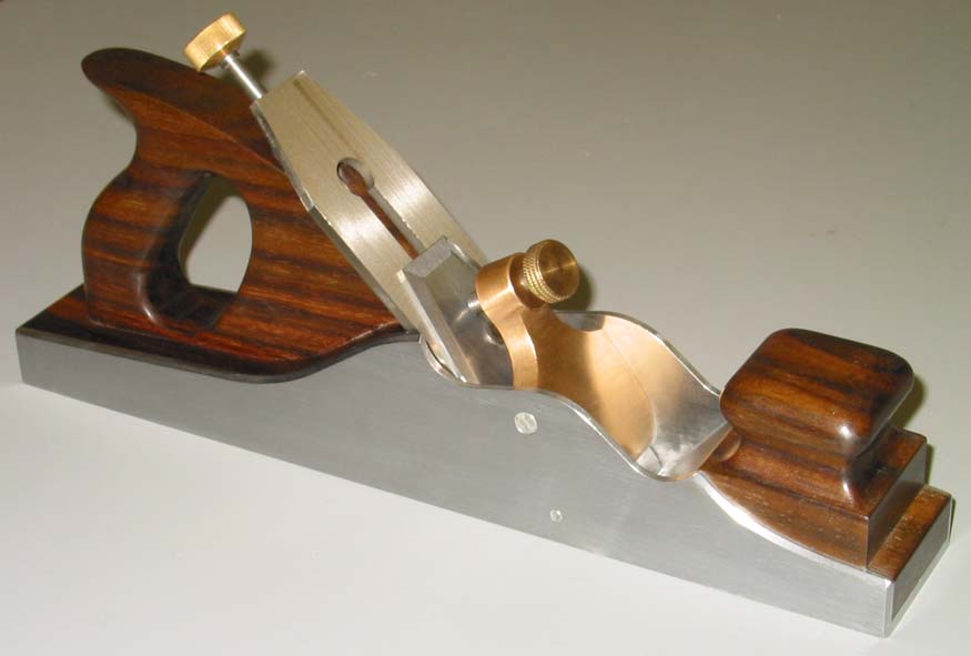
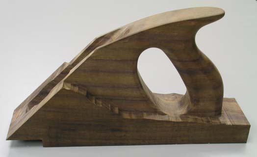
This panel plane is the infill-plane equivalent of the Bailey-style
jack plane, with a sole length of 14". I based the side profile on
the elegant curves of Mathieson's panel plane, but it has an adjuster
and closed tote more like the Norris A1. The front cushion bun is
larger, again closer to the Norris than Mathieson or Spiers' designs.
I chose 2" wide iron for the version of the plane documented here,
which is narrower than the 2-1/4" typical of this type of plane, but
variations are easy: you can modify the design by widening the sole, throat
plate and infill (but you might want to keep the width of the square
"tower" that the cushion bun sits atop at 2", lowering the parts of
the forward infill which flank the tower to follow the curve of the
metal side). I did produce a set of parts for a friend which will
take a 2-1/4" iron, and added 1/2" of length to the front and back of
the sole to mimic the jutting look of the Norris panel planes.
I made the sole by hand-peening double-dovetailed steel plates together,
then filing and lapping everything smooth, in the traditional manner
pioneered by Stewart Spiers. But I had the modern conveniences of
computer software to help me with the design, and a machine shop equipped
with a CNC milling machine and metal-cutting bandsaw. This plane can be
made as I did it, or cut and filed by hand like
Jerome Schueller
did. Wayne Anderson also makes
exquisite infill planes commercially by hand.
I saved some time by purchasing an adjuster and lever cap from Bristol
Design in England. These parts are also available from St. James Bay,
Ray Iles, Spehar Toolworks, and others. My current favorite adjuster
is from Darryl Hutchinson,
who has also supplied me with some nice A2 irons.
The following description lacks some of the depth of the writeup about
a plane I built earlier. For a wordier account of building an infill
smoothing plane, I refer you to
that
article.
Drawings
The following drawings are in PDF format. If you want to print the drawings,
you'll get better results by downloading the Vellum drawings and a viewer
program. See details on the
download page.
 |
Assembly Overview
|
|
|
| Full size (legal paper) Side profile
|
|
 |
Dimensioned Sides and sole
|
|
 |
Full size Infill profile
|
|
 |
Pocket for Bristol Design adjuster
| |
 |
Iron and Back Iron (sized for Bristol adjuster)
| |
 |
Lever cap location (Bristol)
|
|
Link to materials list, excluding tooling,
which is mentioned in my A13 Materials List
Link to machining details
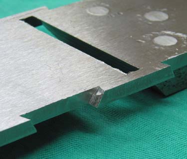
Assembly
|
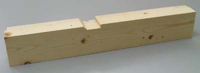
Double dovetails showing parabolic secondary splay milled into sole
|
|
The peening buck, whose sides milled to splay out 0.6° in
anticipation of springback
|
|
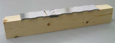
Sole placed on the buck
|
|
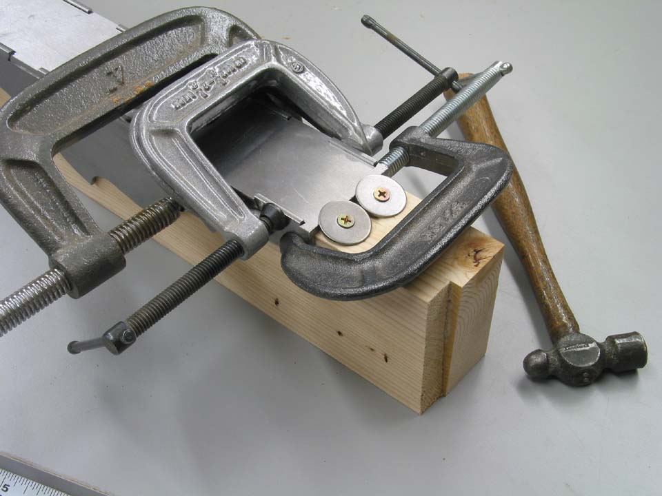
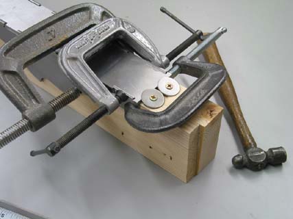
Clamped and ready for peening
|
|
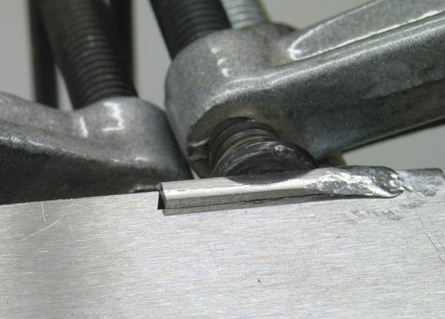
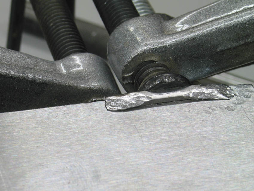
|
|
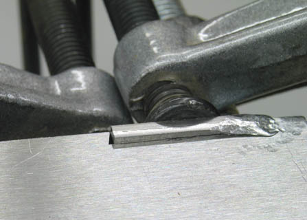
Peening double dovetails: before and after
|
|
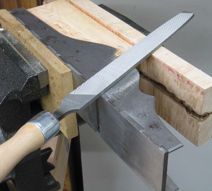
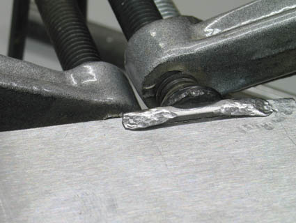
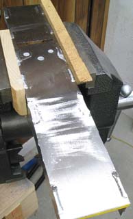
Peening finished, shell removed from buck, starting to file.
Rough filing goes across, then start draw-filing when excess
metal of tails is flush, using finer files.
|
|
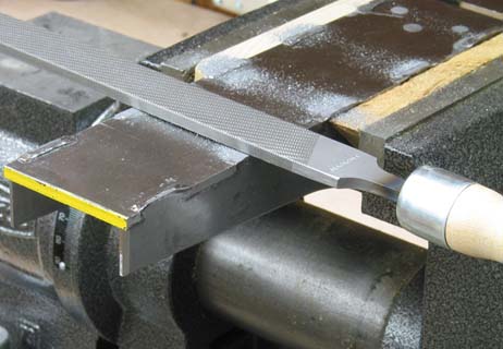
The fun part! Dovetail joints disappear as you file them.
|
|
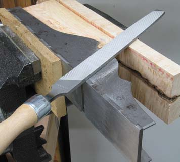
Filing sides flush. Note guide for end of file, to keep from marring upper surface.
|
|
Trial infill pieces, made from scrap to test feel and fit
|
|
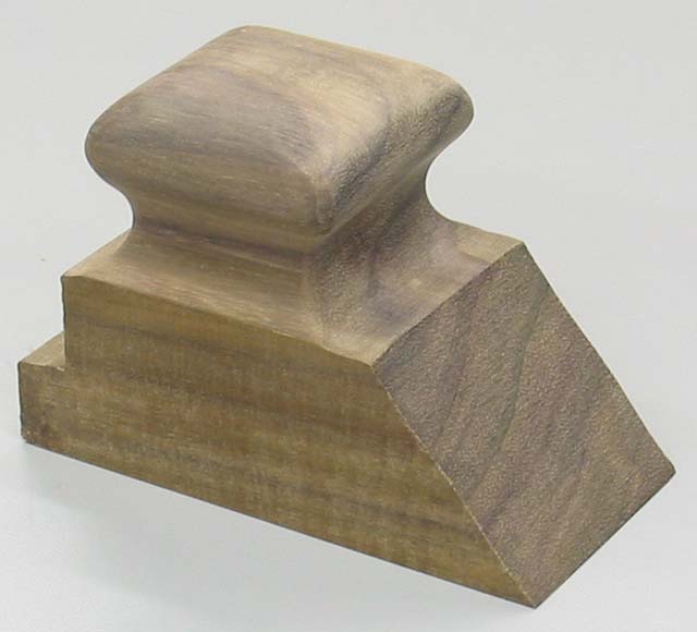
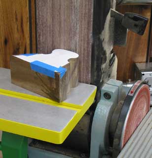
Smoothing bandsaw marks from bun using belt sander
|

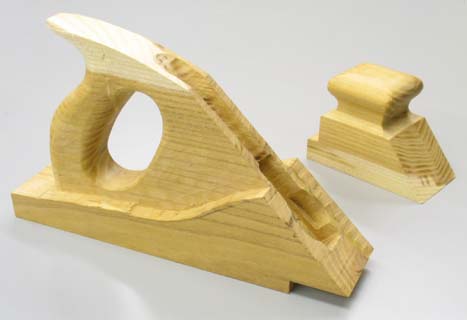
|
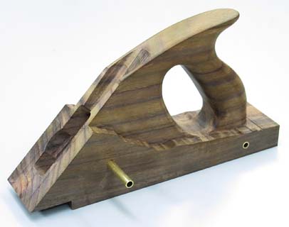
Final bun, roughed from East Indian Rosewood
|

|
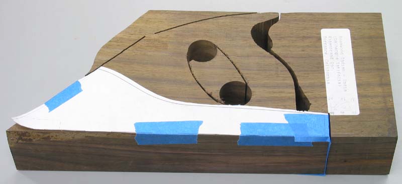
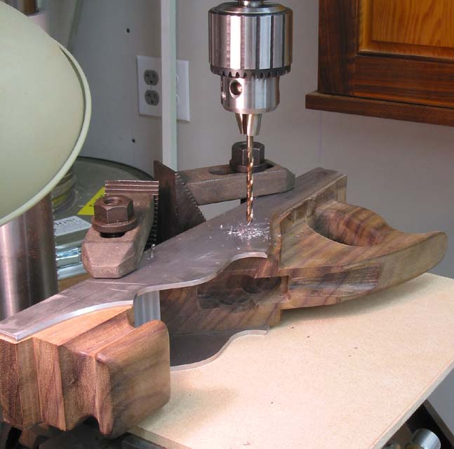
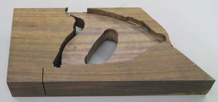
Rear infill profile, rough-cut with bandsaw, Forstner bits and jigsaw
|

|
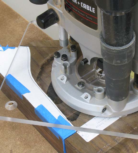
Hogging rear infill to tote width using plunge router
Router base rides on still-attached offcuts
After plunge-routing to tote width (below)
|
|
|
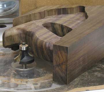
Rough-rounding the tote, using roundover bits
in router table. I used a 3/8" radius for the front and rear
edges of the handle, and a 3/16" radius for the front and top
edges of the finger opening. (Both of these router bits are
flush bearing guided.)
|
|
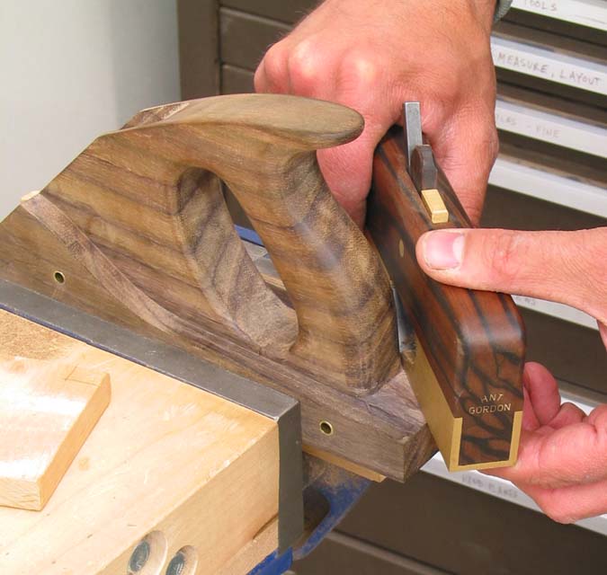
Final tote, in solid East Indian Rosewood
The full-width portion of the rear infill will get trimmed flush
with the metal sides later.
|
I made my own adjuster and lever cap when building a previous infill
plane (see A13 Infill Smoother). It was
a lot of work. This time, I bought commercial parts. If using an
adjuster from another vendor, you may need to customize its mortise
in the tote so that the size, shape and position is correct. The
location of the back iron screw must match the position of the adjuster's
banjo so that the adjustment range of the iron is good. Also, the lever
cap pivot needs to be positioned so that there's enough clearance under
its screw to slip the iron, back iron and screw between it and the bed.
I came up with the oddball pivot arrangement to allow me to remove the
lever cap entirely (e.g. to fiddle with the adjuster). It would
be much easier to rivet a solid shaft in place. Jim Kingshott used a
spring-loaded pair of stepped pins to release his lever caps.
|
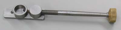
Bristol Design adjuster
|
|
|
|
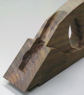
Mortise in tote for adjuster
|
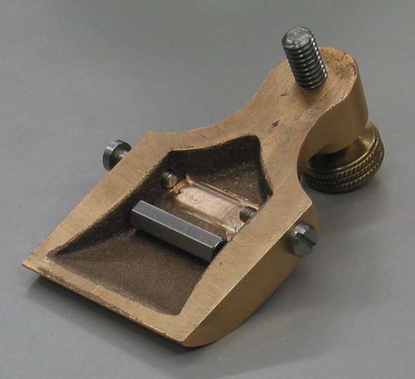
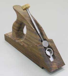
Adjuster in its nest
|

|
Drilling cross pins. I used a spotting drill, then a #16 twist drill
(.177" diameter), followed by a .1855 reamer, then a countersink.
The rod's diameter I used was .185, so the interference fit I usually
try to achieve didn't happen, since I lacked a .184 reamer.
|
|
Brass spacers/liners through which the cross pins are installed.
The length of these brass tubes should be exactly the width between
Inside faces of the shell's sidewalls. A piloted counterbore
is helpful to keep the larger-bored hole concentric with the initial
bore. (Pilot size = 3/16, countebore size = 1/4")
|
|

|
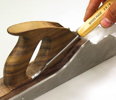
Shaving down the lower edge of the finger opening
to final shape using a back-bent gouge.
|
Bringing the bandsawn "rear deck" flush
|
|
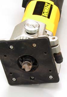
The short top-bearing-guided flush trim router bit I use: Eagle
America 102-1002B "Dado cleanout" bit. It takes two passes.
|
|
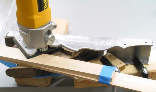
Trim router, jigged for flush trimming. Note the complementary
wedges (table leg taper offcuts, actually) held together so that
the free-hanging side of the router base can ride on something.
Sliding the pair of wedges lengthwise against each other gives
you precise control over their combined thickness. After the
first pass, remove the thin fin, taking it down to flush with
the metal side (and the infill wood below). Now you can make
the second pass, the bearing being guided by the cut you just
made. Setting the depth of cut is obviously important before
the second pass.
|
|

|
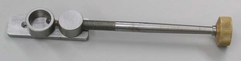
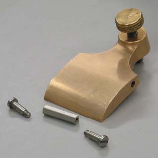
Bristol Design lever cap, with pivot shaft made from shoulder
screws and a hex threaded spacer ("coupling nut").
A bit of brass had to be milled from underneath to allow clearance
for the hex coupler to fit into.
When assembled, the screw heads pivot in holes drilled and reamed
into the plane's sidewalls.
|
|
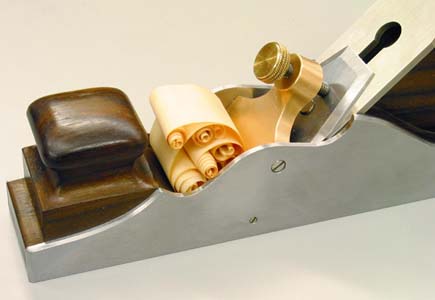
Infill riveted, sides filed, lever cap and blade guides installed.
Only after flattening/lapping/polishing the sole do you file open
the mouth.
|