lunar module stability


|
|
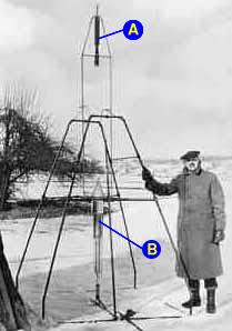
The classic early skyrocket shown in Fig. 1 attaches the rocket proper to a long thin stick. The stick would drag in the air behind the rocket and help keep it on a straight course, much like the tail fins on later rockets. By placing a large aerodynamic area behind the rocket's center of gravity, and keeping in mind that all rotations will be about the center of mass, the rocket designer can arrange that wind pressure will push the back of the rocket back into line behind the rocket's center of mass.
|
This turned out not to be the case; it doesn't matter whether the center of thrust is above or below the center of mass. And since it's impractical to put the fuel supply beneath the nozzle where hot exhaust gas will strike it, Goddard returned to the traditional fuel-on-top configuration and provided broad tail fins to allow for aerodynamic stabilization.
This is passive stabilization -- designing a rocket so that the act of tipping out of alignment will automatically result in a force that brings it back into line. Active forms of stabilization were also considered, especially for rotational forces that exceeded the ability of passive features to correct it. This is extremely important for military rockets and other rockets that must fly very precisely to their destinations.
Early rocket scientists realized that if they could tell when the rocket was tipping and apply a correction quickly enough, they could stop the tip before it became a fatal tumble. To detect tipping, you need some reference against which to measure the orientation of the rocket. Then you need some way to rotate the rocket back to its intended orientation. And all this has to work quickly enough to catch rotation before it becomes too serious.
Here is a more detailed discussion of how that is typically done.
PUTTING IT ALL TOGETHER
IN THE LUNAR MODULE
The active forms of stabilization are very important to the lunar module's design because there is no air to push against fins and realign the rocket if its axis points in a different direction than its flight path. Aerodynamic stabilization was not an option. Hence the lunar module designers turned to a sophisticated, computer-controlled active guidance system.
The lunar module had two stages, one used for the descent and another for the return to lunar orbit and rendezvous with the command module. The descent stage engine had a throttle to control the amount of thrust. The engine was also gimbaled (Fig. 3d) and could swivel up to 6° in either side-to-side direction. And of course it had a set of RCS thrusters (Fig. 3e).
|
In fact, the lunar module was essentially "fly-by-wire". The pilot's hand controller was not usually directly wired into the engine gimbal or RCS system, although it could be. Most often it simply told the computer which direction the LM should move -- left, right, forward, or backwards. The computer adjusted the gimbal angle to produce the desired lateral motion. The pilot was not required to manually maintain the LM's balance.
The problem of shifting centers of mass in rockets had been solved by the 1940s. It's simply ridiculous to suppose that the lunar module provides any special difficulty. In fact, we'll see below that it's actually easier to keep the lunar module from tumbling than it is to control a common cylindrical rocket.
 But the lunar module
ascent stage engine could not gimbal. It was fixed in place. It was
therefore too unstable to fly.
But the lunar module
ascent stage engine could not gimbal. It was fixed in place. It was
therefore too unstable to fly.
First, the same computer that controlled the descent also controlled the ascent. The same RCS that used to help control the descent performed all of the attitude control for the ascent. As the off-axis thrust caused the ascent stage to rotate, the RCS jets fired to counter the rotation and return it to the correct attitude. This is why the films of the LM ascent seem to show a periodic sway or oscillation: the RCS "fought" the off-axis ascent engine.
|
Second, the LM ascent stage is a much more inherently stable spacecraft than a cylindrical rocket from an inertial point of view. (Keep in mind a rocket that flies through air can use the air to make it overall very stable.) Fig. 6 shows a front view of the LM ascent stage and the location of the people and things that affect the vehicle's center of mass.
The ascent engine is mounted inside the spacecraft, not attached to the bottom of it. This places the center of mass very near the center of thrust, limiting the rotational effect of off-axis thrust. In fact, during the first few seconds of the ascent the centers of thrust and mass are very close together.
The most massive component of any spacecraft like the lunar module is fuel. The fuel tanks are mounted as low as possible, and carefully balanced left-to-right. (Oxidizer is denser than fuel and therefore the fuel tank is positioned farther outboard.) Though not shown in Fig. 6, the RCS fuel tanks are mounted behind the astronauts, helping to balance the spacecraft front-to-back.
The astronauts are inboard of the fuel tanks and are considerably less massive. Their motion is further restricted by the cramped cabin. Thus the idea that the movements of the astronauts would spell doom for a stable ascent completely ignores the fact that the much more massive fuel is mounted farther outboard where it has a greater effect due to its steady depletion. In fact, the massive fuel tanks would actually damp, or lessen, the effects of the astronauts' movements in the same way the long pole carried by a tightrope walker increases his balance.
Note also the extreme outboard position of the RCS thrusters. They are mounted on outriggers to increase their moment arm (rotational force). For small rotations, the thrusters are fired in "pulse mode" which uses very short bursts.
ANATOMY OF A
TUMBLE
The theory of balancing on a rocket on its thrust (neglecting aerodynamic effects) is pretty simple. In most spacecraft the center of thrust (c.t.) and center of mass (c.m.) are arranged as in Fig. 7a. The center of mass is the point around which the spacecraft will naturally rotate, and the point at which the force of gravity (if any) will act (Fig. 7b). The center of thrust is the point at which the force of the engine is applied (Fig. 7c), generally the throat of the engine.
|
If the rocket engine is correctly trimmed, the engine will be gimballed so that the thrust vector (T in Fig. 7c) points along the line joining the centers of thrust and mass. But if the center of mass changes -- e.g., an astronaut moves or the fuel sloshes in the tanks -- the thrust vector T will no longer point in the right direction.
|
Let's briefly consider only the rotational component, Tr. If the center of thrust is far away from the center of mass, Tr acts with more leverage to rotate the spacecraft (Fig. 8a). If we move the engine closer to the center of mass (Fig. 8b), we reduce the leverage and therefore reduce the torque, or twisting force, that is applied to the spacecraft. The plumber's trick of slipping a length of pipe on the handle of the wrench in order to break loose a rusted joint is an application of this principle.
|
But the main source of mass in the ascent stage is the fuel tanks, whose centers are located far below the visual center of mass. This would offset the center of mass downward. While computing the actual center of mass is a very complicated and tedious process, we can be sure that the center of mass does not lie any higher than the astronauts' chest, and likely lies far lower -- perhaps even below the center of thrust.
How can you say the
lunar module ascent stage is a more inherently stable design? A
cylindrical rocket's moment of inertia is greater than that of the
roughly spherical ascent stage. That means a cylindrical spacecraft
will resist torque more than a spherical one, and is therefore a
better design.
This is a valid observation according to physics, but its effects are overshadowed by the position of the LM ascent engine and the resulting substantial reduction in moment.
JUST A
MOMENT
"Moment of inertia" is the rotational equivalent of mass. Newton's laws of motion clearly say that a mass will resist attempts to move it (or stop it if it's already moving), and the resistance is proportional to the mass of the object. Similarly, a mass will resist attempts to rotate it, and the resistance is proportional to a combination of the object's mass and shape. Long, skinny objects resist changes in rotation more than spherical objects of the same mass. This is intuitively obvious to those who have ever carried lumber. You shoulder a plank, balancing its center of mass over your shoulder. But as you turn your body you find that the plank doesn't want to rotate with it, and once it's turning it doesn't want to stop. The art of baton twirling is based on the high moment of inertia of such an object.
Consider two hypothetical spaceships of identical mass, containing identical volumes. One is spherical, while the other is cylindrical. The length of the cylinder is five times its diameter (an arbitrary choice). The radius of the resulting cylinder will be about half the radius of the spherical spacecraft.
In this case the cylinder will have more than five times the moment of inertia as the sphere. In other words, it would take five times as much torque to produce the equivalent rotation rate in the cylinder as in the sphere, even though they have identical mass.
But as we discussed above, the answer lies in how close to the center of mass our engine is placed. In the cylindrical spacecraft (i.e., a rocket), the engine is placed at one end of the cylinder. If we place the sphere's engine anywhere on the surface of the sphere, the engine in the cylinder will produce about 2.5 times more torque because it's so far away from the center of mass. Factoring in moment of inertia, the rotational acceleration of the sphere will be about twice that of the cylinder for the same amount of off-axis thrust.
If, as in the case of the LM ascent stage, the engine is placed inside the sphere, closer to the center of mass, the amount of torque produced by off-axis thrust is greatly reduced. In fact, we would have to move it inward by only about half the radius in order to equalize the situation, and if we placed it at 1/3 the radius we will have achieved a more stable design than the cylinder, even though the sphere doesn't resist rotation as well as the cylinder.
The best evidence for the stability of the LM design is empirical. Find a yardstick or meter stick. Try to balance it vertically on end on your hand. You probably won't be able to do it for very long. But balance it horizontally, using the graduations as a guide in finding the center of mass. You should be able to do this easily, and may even be able to move your hand around without upsetting the stick. The mass and moment of inertia are identical in these cases, but you apply less torque by off-axis support when the stick is horizontal.

