My amateur telescope making page
The "Deep Space Scope" Design
Home | Astronomy | DS-3 | Plop DesignOverview
The mirror cell for DS-3 was created using experience, guesswork and trial and error. These worked quite well, but there should be a better way. Fortunately, there is. It is a program called Plop. See the section "Sources and Supplies" for where to find and download Plop. I want to thank Toshimi Taki for the original formulas (Sky & Telescope, April 1996), and especially David Lewis for creating the graphical program Plop. David, you did the ATM community a great service!A few important issues about plop:
- All measurements are in millimeters. Multiply inches by 25.4 to get millimeters. Also, divide millimeters by 25.4 to get inches.
- Human vision is most sensitive to light in the 500 nanometer range (0.0005 millimeters)
- Plop returns PV (Peak to Valley) analysis as millimeters. To get fractional wavelengths of error, use this formula: WaveFracDen = 0.0005 / PV.
- Colour Plot shows highs and lows as red and blue, with middle ground shown as green. Green is good, red and/or blue are BAD.
- BUT - Plop scales highs and lows, thus ALWAYS shows red and blue. As recommended by Mark Holm on the ATM list, use the following setup options: in Colour Plot, Options, Picture Options, Z-axis range in plots, insert 0.00003125. This represents a 1/16 wave mirror, or a 1/8 wave P-V mirror at the eyepiece.
- Note that we are talking about errors due to the mirror
cell. Errors in the mirror will ADD to these mirror cell
induced
errors.
A few items about DS-3 and simulating it's mirror cell:
- I used three series of six support points to simulate DS-3's mirror cell.
- The 12" mirror for DS-3 is made from BK7 glass.
Input parameters that model a 3 support cell (NOT DS-3's cell) are as follows:
- Primary mirror diameter: 304.8mm
- Primary mirror thickness: 38.1mm
- Focal length: 1524mm
- Secondary mirror diameter: 52.1mm
- Modulus: 8100
- Poisson: 0.208
- Density: 2.51e-6
- 1 ring, 3 support points.
- Support radius: 0.409 percent from center.
Results of a 3 support system:
- Visible P-V Error: 2.21747e-05mm
- Visible RMS Error: 4.991e-06mm
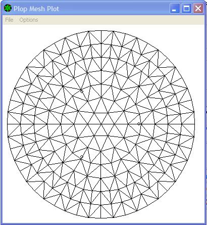
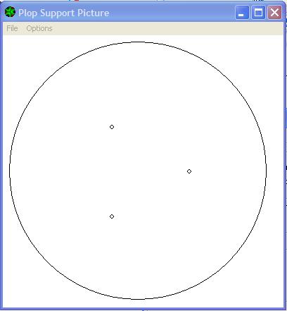
Here is the mesh that PLOP created, and the location of the three supports.
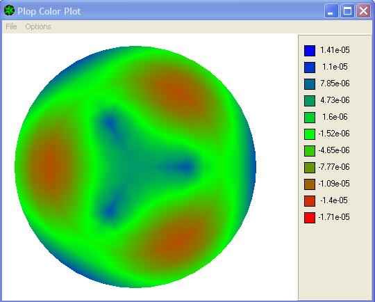
Color plot of the deformities of the mirror. Blue is high, red is low.
Input parameters that kind of simulate DS-3 that I used for plop are as follows:
- Primary mirror diameter: 304.8mm
- Primary mirror thickness: 38.1mm
- Focal length: 1524mm
- Secondary mirror diameter: 52.1mm
- Modulus: 8100
- Poisson: 0.208
- Density: 2.51e-6
- 6 rings, 18 support points. (E-mail me if you
want details)
- Support radius: Variable
Results:
- Visible P-V Error: 2.37061e-05mm
- Visible RMS Error: 5.46034e-06mm
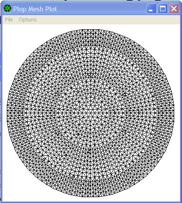
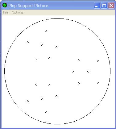
Here is the mesh that PLOP created, and the location of all of the supports. I am trying to model the pads that hold the mirror.
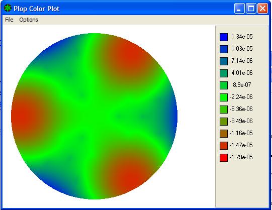
Color plot of the deformities of the mirror. Blue is high, red is low.
Conclusions:
- Assuming a perfect mirror, the P-V numbers translate into a
1/21
wave mirror cell. This is 10.5 wave at the
eyepiece. Ummm.
- The mirror cell that I used on DS-3 was theoretically acceptable, but no better than acceptable.
- In real life, this mirror cell works well. Since I am pretty sure that Plop is mathematically correct, I can only assume that the standard that I set for this analysis is strict enough. BUT, I wouldn't want it to be any worse!
- It turns out that if the most outside supports are widened,
which
would be true for supports that were triangles rather than circles, the
mirror cell is MUCH better. Sounds like a great rainy weekend
project.