
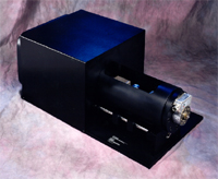
 The FT 201 Loading Module is designed specifically to test specimens for plane-strain fracture toughness in accordance with ASTM standard method E 1304. Fracture toughness test specimens tested by method E 1304 are commonly referred to as Short Rod (SR) specimens. The FT 201 Loading Module is a table top unit which applies an opening load to a properly prepared Short Rod test specimen. It incorporates transducers to measure the specimen mouth opening load and the mouth opening displacement. Separate modules are required to control the loading module and to acquire and display the test data.
To perform a fracture toughness test, an SR specimen is placed in the loading module, over the two specimen loading grip halves. The SR specimen has a grip groove (a simple rectangular slot) machined in one end. This grip groove fits over the two loading grip halves. The SR specimen mounts vertically in the loading module, making it easy to place the speciman in the module and keep it properly positioned during the test.
Mouth opening load is applied to the SR specimen by moving the two specimen loading grip halves apart. One half of the grip set is mounted directly to the load cell. The load cell thus provides a direct and accurate measurement of force applied to the SR specimen. The other grip half is mounted to a high precision drive screw. The drive screw is driven by a variable speed electric motor to provide exact control of mouth opening (and hence crack advance) speed. Both grip halves are mounted on a common pair of guide rods by means of ball bushings to provide precise alignment of the grips.
Several options are available for monitoring specimen mouth opening displacement. An external clip gauge can be mounted to the outside diameter of the SR specimen to measure mouth opening directly. Alternatively, a displacement transducer can be mounted in the moving grip half, providing a measurement of relative grip movement during the test.
Features:
|
Specifications - FT 201 Loading Module:
|
12,000 |
|
250, 500, 1000, 2500, 5000, 10000, 15000 |
|
0.25, 0.50, 0.75, 1.00, 1.50, 2.00 |
|
0.02 to 0.85 |
|
30" x 14" x 11" |
|
200 |
|
Manual control - FT 202M Automated control - FT 202A |
Options
|
0-5 VDC, 0-20 mA, 4-20 mA |
Selecting an appropriate load cell range.
To select a load cell of the appropriate range for plane-strain fracture toughness measurements of a particular material, the user must first decide what size SR specimens will be tested. This depends on the size of material available to prepare SR specimens. In addition there is a minimum SR specimen diameter (B dimension) that must be met in order to achieve a valid test result for any particular material. In general terms, the B dimension of the test specimen must be large enough to assure that plane-strain conditions predominate at the crack tip. Specifically, the specimen must be of a size so as to satisfy the following equation:

where:
- B is the specimen diameter,
KIv is the fracture toughness and,
Sys is the tensile yield strength of the material.
Once a test specimen diameter has been determined, the table below can be used to select a load cell of the appropriate range.
The maximum load capability of the FT 201 Loading Module is 12,000 lbs. as specified above. Load cells of different ranges can be installed on the loading module in order to allow load measurements to be made as accurately as possible for the material being tested. In general, it is desirable to make fracture toughness measurements where the peak load for the material being tested is approximately 50 - 75% of the rated load of the load cell. Measurements as low as 10% of the rated capacity of the load cell are possible, with some loss of resolution. The table below is provided to help the user select the load cell range or ranges that would best suit the materials to be tested. The table indicates the fracture toughness (ksi√ in) that corresponds to the maximum load of a specific load cell and for a specific specimen diameter.
| Load Range |
| Dia (B) | 250 lbs | 500 lbs | 1,000 lbs | 2,500 lbs | 5,000 lbs | 10,000 lbs | 12,000 lbs |
| 0.25 in | 48 | 97 | 194 | --- | --- | --- | --- |
| 0.50 in | 17 | 34 | 69 | 170 | --- | --- | --- |
| 0.75 in | 9 | 19 | 37 | 93 | 187 | --- | --- |
| 1.00 in | 6 | 12 | 24 | 60 | 121 | 242 | --- |
| 1.50 in | 3 | 6 | 13 | 33 | 66 | 132 | 158 |
| 2.00 in | 2 | 4 | 9 | 21 | 43 | 86 | 103 |