Using Short Rod Specimens
Failures of structures due to brittle fracture under conditions of low stress have been recorded over the last two centuries. Since World War II, the use of high strength materials has increased significantly. The aviation industry in particular has demanded higher and higher strength-to-weight ratios, resulting in the development and application of very high strength materials. Unfortunately, many of these new high strength materials have little resistance to growth of cracks (fracture toughness). Thus, in some structures, the presence of small flaws resulted in failures of these high strength materials at stresses well below those for which the structure was designed. The occurrence of low stress fracture in high strength materials led to the study and development of Fracture Mechanics.
Standard Method E 399
 With recognition of the importance of Fracture Mechanics in the analysis of structures came the need for a method to measure a material's ability to resist the growth of cracks. A standard test method to measure this important material property, mode I plane-strain fracture toughness, was developed during the 1960's. This standard test method was published in 1970 by ASTM as standard E 399-70, "Standard Test Method for Plane-Strain Fracture Toughness of Metallic Materials."
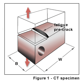
E 399 allows a number of test specimen configurations. The most commonly used test specimen is the Compact Tension (CT) specimen. A CT specimen is shown in Figure 1. More than a decade of research went into the development and refinement of this test method to make it relatively straight forward. The basic idea is to measure the tensile (opening) load required to advance an existing crack in the test specimen. To develop a natural crack, the CT specimen is machined with a slot part way through the specimen. The CT specimen is loaded cyclically with a tensile maximum stress. The cyclic loading causes a fatigue crack to develop at the tip of the machined slot in the specimen. Once this fatigue "pre-crack" has grown to an adequate length, fracture toughness is measured by increasing the tensile load (Mode I loading of the crack) until the crack rapidly advances, fracturing the test specimen into two halves. A load-displacement record is made of this final loading. Based on a physical measurement of the fatigue pre-crack length, a polynomial expression for the compliance of the CT specimen is used to calculate a conditional value of fracture toughness for the material. Criteria in the E 399 standard are evaluated to determine if the conditional value is a valid plane-strain fracture toughness (KIc) value.
Standard method E 399 has been used to measure the fracture toughness for a wide variety of materials. It has been very useful in developing a large data base of plane-strain fracture toughness values for many materials.
Standard Method E 1304
 In 1976 L.M. Barker proposed the Short Rod (SR) test specimen for measuring plane-strain fracture toughness. This new test method was designed to simplify plane-strain fracture toughness procedures and to allow a broader range of materials to be tested successfully. These objectives were accomplished by designing a test specimen which would develop a natural crack in the specimen without the need for fatigue pre-cracking. In addition, the test specimen was configured to allow a much smaller test specimen to be used for a valid test than is possible with the CT test specimen. With these two significant advantages, the SR test specimen was initially used to successfully measure plane-strain fracture toughness in brittle materials (tungsten carbides and ceramics). Based on its success in testing brittle materials, the SR specimen was then used on materials that had traditionally been tested by method E 399. Comparative test results showed that the two test methods produced ASTM acceptable results for plane strain fracture toughness. Work began to develop an ASTM standard test method based on the SR specimen. The result was ASTM Standard Method E 1304, "Standard Test Method for Plane-Strain (Chevron-Notch) Fracture Toughness of Metallic Materials," first adopted in 1989.
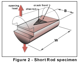
As illustrated in Figure 2, the general shape of a SR test specimen is a right cylinder. Two narrow slits are cut in the sides of this test specimen such that the two specimen halves are joined by a triangular ligament of material (chevron). The test procedures are very similar to those for a CT test specimen, except that no fatigue pre-crack is required. In this case, a tensile (opening) load is applied to force the two specimen halves apart (Mode I loading). When this mouth opening load reaches an adequate level, a natural crack is initiated at the tip of the chevron. The geometry of the test specimen is such that as the crack advances, the crack front broadens, thus a crack grows stabily, even in very brittle materials. At a crack length known as the "critical crack length", the crack becomes unstable (requires lower rather than higher loads to advance the crack). A load-displacement record is made during the test. To evaluate fracture toughness, the load to advance a crack of specific length must be known. This may be at the geometry-dependent "critical crack length", the point at which the load is a maximum, or it may be the load at some other crack length. The crack length at any point during the test may be determined using a compliance technique. During the specimen loading, a pair of unloading-reloading cycles are performed. By comparing the slope of the reloading curves to the initial loading slope, the crack length can be determined. With this technique, fracture toughness can be measured at several different crack lengths as the crack propagates through the test specimen.
Minimum specimen size requirements for fracture toughness test specimens are based on the requirement that the crack front must be subject to plane-strain conditions. The flank ends of the crack, where the crack intersects a free surface, are, however, in plane-stress conditions. The test specimen width (B dimension) must be large enough such that the plane-stress effects at the flank ends of the crack are minimal. In a CT specimen the size of this plane stress portion of the crack front is a function of the plastic zone size at the tip of the crack. In the SR specimen, rather than intersecting a free, essentially infinite surface, the crack flank ends intersect very narrow slots (0.015 in.). The very small height of this "free surface" tends to restrict the size of the plane-stress portion of the crack front to approximately the size of the slots. Therefore, the size of the plane-stress zone at the flank ends of the crack in a SR test specimen are much smaller than the plane-stress zones at the flank ends of a crack in a CT specimen and a minimum-sized SR specimen can be significantly smaller than an equivalent CT specimen. Specifically, E 1304 allows a minimum SR test specimen diameter (B) that is one half the minimum "B" dimension of a CT test specimen of the same material. This results in a SR test specimen volume that is only 3% of the volume of an equivalent CT test specimen.
TN 501 | TN 502 | TN 503 | TN 504 | TN 505 | TN 506