Using Short Rod Specimens
ASTM standard test method E 1304, "Standard Test Method for Plane-Strain (Chevron-Notch) Fracture Toughness of Metallic Materials," significantly simplifies measurement of plane-strain fracture toughness. This test method was first proposed in 1976 and was accepted as an ASTM standard in 1989. This test method allows measurement of fracture toughness using smaller test specimens and simpler test procedures than previous fracture toughness tests. This Technical Note summarizes test procedures as outlined in E 1304.
Specimen Preparation
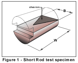
 One of the advantages of the test method is the simplicity of the test specimen geometry. E 1304 allows five different specimen geometries. These include specimens of round (rod), square, and rectangular (bar) cross section with a length to diameter ratio (W/B) of 1.45 or 2.00. A grip groove is machined in one end of the short rod or short bar specimen. This grip groove is a rectangular groove machined in one face of the specimen, to provide loading surfaces where the grips in the test machine can apply an opening load to the two specimen halves. The grip groove must be parallel to the plane in which fracture toughness is to be measured. A piece of test material machined to the proper diameter (or other standard cross section) and length, with a grip groove in one end, is called a specimen blank.
The most critical part of specimen preparation is machining the chevron slots in the specimen blank. These narrow slots (typically 0.015") are generally machined with a slitting saw blade of material appropriate for machining the test material. Two slots are cut at opposing angles, the result being that the two specimen halves are now joined by a triangular ligament of material (Chevron). A typical test specimen is shown in Figure 1.
Specimen Size Criteria
In fracture toughness testing, to obtain a valid test, a minimum specimen size must be used. This minimum size is intended to assure that the majority of the crack front, at the time of the fracture toughness measurement, is under plane strain constraint. The criteria that has been established for a valid test is:

where:
- B is the specimen diameter,
KIv is the fracture toughness and,
Sys is the tensile yield strength of the material.
Test Procedures
 To measure plane-strain fracture toughness, one must measure the load required to advance a crack of known length in the test specimen. To accomplish this, a properly prepared test specimen is placed in a test machine, with the specimen grip groove over a pair of opposing loading grips. When the loading grips are moved apart, an opening load is applied to the two specimen halves. Transducers in the test system monitor the magnitude of the opening load as well as the specimen mouth opening displacement. The test record plots mouth opening displacement vs. mouth opening load.
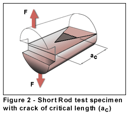
As opening load is increased, specimen mouth opening displacement increases as the test specimen is deformed elasticly, until the load reaches a point at which a natural crack is initiated at the tip of the triangular ligament (chevron) that joins the two specimen halves. As the load increases further, the crack length increases. The triangular shape of the fracture surface area dictates that as the crack length increases, the width of the crack front also increases. This widening of the crack front requires more energy to grow the crack, resulting in a stable, steady-state, natural crack. At a crack length known as the "critical crack length" (ac), the load required to advance the crack passes through a maximum, and less load is then required to advance the crack. This critical crack length is geometry dependent and therefore a known length for the test specimen. In the simplest form of the test, one can simply measure the maximum load, and, knowing the critical crack length, then calculate plane-strain fracture toughness for that test specimen.
In some instances, it is desirable to make a fracture toughness measurement at a crack length other than at the critical crack length, or at a load other than at the peak load. In these cases, it is necessary to know the crack length at a particular load. In a short rod test, the crack length at any point in the test, can be measured by a compliance technique. This is done by performing an unloading-reloading cycle several times during the test. The loading slope of the load-displacement test record is a function of the length of the crack between the two specimen halves. The shorter the crack length, the stiffer the two specimen halves are in bending, and the steeper the slope on the load-displacement record. Compliance calibrations have been done for the short rod family of test specimens so that by comparing the slope of a reloading cycle at some crack length, to the initial loading cycle slope (prior to any crack growth), the length of the crack at that point can be determined.
Two different types of test records are obtained in short rod fracture toughness tests. The first is referred to as "smooth crack growth behavior." In this case, the crack length increases continuously with increasing mouth opening load. The second type of behavior observed in some materials is called "crack jump behavior." In this type of material, a crack initiates at some critical load. Upon initiating, the crack advances a finite distance and then arrests. The crack then remains at this arrest point until some new critical load is achieved, and the crack then advances rapidly (jumps) once again until it reaches a new arrest point. Typical load-displacement test records for these two types of behavior are discussed in the following paragraphs.
Smooth Crack Growth Behavior
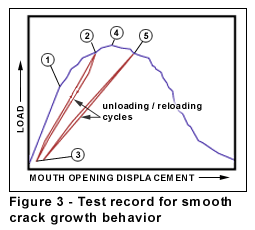
 A typical load-displacement test record for a material exhibiting smooth crack growth behavior is shown in Figure 3. The initial loading slope is linear, as the two specimen halves deform elasticly, prior to crack initiation. As a crack is initiated at the tip of the chevron, the load-displacement curve deviates from the initial loading slope (point 1), becoming more flat.
As the crack length increases, the load required to advance the crack also continues to increase until the crack reaches the critical crack length. At a point prior to the critical crack length (2), the operator stops the movement of the test machine grips and reverses the direction of the grip movement to initiate an unloading cycle. The load continues to be decreased until the load is about 5% of the maximum test load (3). The grip direction is then reversed again to begin reloading the test specimen.
The reloading curve is essentially linear, indicating no additional crack advance, but at a smaller slope than the initial loading slope, due to the elastic deformation of the now longer test specimen halves. When the load reaches the load at which the initial unloading cycle was initiated, the crack once again begins to advance and the load-displacement curve follows the typical rounded behavior, passing through a maximum load (4) as the crack reaches the critical crack length. At a point beyond the critical crack length (5), a second unloading-reloading cycle is initiated. Upon completion of this second cycle, the grips continue to be moved apart until the crack advances entirely through the test specimen and the load drops to zero.
For each unloading-reloading cycle, a slope ratio (ratio of the slope of the reloading line to the slope of the initial loading line) is determined. Based on this slope ratio, a crack length is determined. Crack length can then be inferred by interpolation at any point between the two unloading-reloading cycles. Thus, plane-strain fracture toughness can be calculated at any point in this area of the curve as well. Typically this calculation is made at a slope ratio corresponding to the critical crack length and maximum load.
Crack Jump Behavior
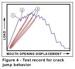
 A typical load displacement record for a material exhibiting crack jump behavior is shown in Figure 4.
As in the smooth crack growth case, the initial loading slope is linear. In this case, however, when the crack initiates (1), there is a drop in the load as the crack advances suddenly (jumps) a finite distance and then arrests (2). As the load is then increased, the loading slope is again linear, indicating no crack advance, until a new critical load is reached and the crack jumps again. This process is repeated as the crack propagates through the test specimen in discrete increments or jumps. Some materials exhibit rather small crack jumps (as in the test record in Figure 4). Other materials exhibit much larger jumps (the crack travels a greater distance before arresting). When a crack arrests somewhere in the vicinity of the critical crack length (3), an unloading-reloading cycle is performed to determine the crack length prior to the next crack jump. These unloading-reloading cycles are conducted for each significant crack jump where the slope ratio is within 20% of the slope ratio for the critical crack length. A specific plane-strain fracture toughness value can be calculated for each such crack jump in much the same way that it is calculated for smooth crack growth materials at points other than at the critical crack length.
Note that if one were to draw a curve though the maximum points on the load-displacement record for the crack jump case, the resulting curve would look very much like the test record for the smooth crack growth material. In this case, the value of fracture toughness calculated for each crack jump would be the same. This points out one of the advantages of this method of measuring plane-strain fracture toughness. Fracture toughness can be measured at a number of different points over a finite crack length. Thus, in cases where fracture toughness varies as a function of crack length, either due to variations in toughness in the material itself, or due to "R-curve" effects, different toughness values can be measured at different crack lengths. In these cases, the "normal" load-displacement test record is skewed one direction or the other, depending on whether fracture toughness is increasing or decreasing with increasing crack length.
TN 501 | TN 502 | TN 503 | TN 504 | TN 505 | TN 506