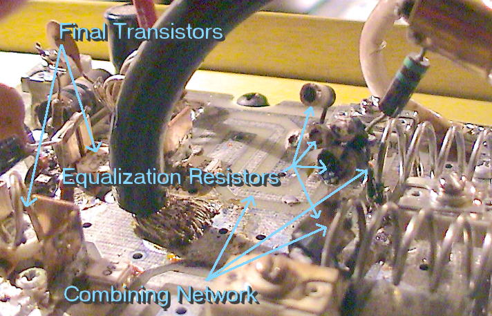
Shown above is a closeup view of the PC board in 62's power
amplifier prior to repair. The large black lead near the center
is the negative lead from the power supply. It must deliver about
20 amps to the board.
Clint, KA7OEI, speculates on the series of events that led
to the complete failure:
- Sometime between 11/05/03 and 12/30/03, one of the two final
transistors in the '62 amplifier failed. By 12/30/03, the output
power was likely in the 20-25 watt area instead of the normal 130 watts.
- The 100 watt amplifier is actually two 40 watt amplifiers in parallel
(the transistors used are rated at 40 watts each at 175 MHz and are
easily capable of more than this at 2 meter frequencies.) Their outputs
are combined, yielding the full output power. Inevitably, the two
amplifiers aren't going to put out exactly the same amount of power,
and equalizing resistors are placed between the two amplifiers to
help "power sharing" and to soak up some of the mismatch. With one
failed amplifier, the pair's balance was upset, causing the resistors to
have to dissipate much more than their power ratings.
- With the resistors having to dissipate way too much power, they burned
open. This, coupled with the imbalance, probably put additional stress
on the remaining device - which was now poorly matched with the load.
Additionally, the "dead" amplifier section was no longer properly matched
to the driver stage - something that could both present a mismatch to the
driver and/or cause additional/excess drive power to appear on the
remaining stage.
- The mismatch probably excessively stressed both the driver and the final
stages. It is likely that the remaining final stage failed due to these
stresses and was followed in relative quick succession by the driver stage -
which after failure of the last final, likely experienced a catastrophic
mismatch.
|